Thermal printer

a printer and moving device technology, applied in the field of thermal printers, can solve the problems of increasing the size and production cost of the thermal printer that must have the moving means such as the recording material guide, and achieve the effects of reducing the frequency of contact, increasing the size and production cost of the apparatus, and preventing dirt from adhering

Inactive Publication Date: 2008-04-01
FUJIFILM CORP +1
View PDF4 Cites 2 Cited by
  • Summary
  • Abstract
  • Description
  • Claims
  • Application Information

AI Technical Summary

Benefits of technology

[0012]Although the thermal printer disclosed in JP 2002-292953 A can reduce the frequency of contact between the lateral edge surfaces of cut sheets of a recording material and specified heating elements, the thermal printer that must have the moving means such as the recording material guide involves increases in the size and production cost.
[0013]An object of the present invention is to provide a thermal printer capable of reducing the frequency of contact between a thermal recording layer exposed in the lateral edge surfaces of cut sheets of a recording material and a specified portion of a thermal head without causing an increase in the production cost or the apparatus size, whereby dirt is prevented from adhering to the specified portion of the thermal head to enable a high-quality image to be recorded without causing streaky density unevenness due to a decrease of the color optical density on the specified portion of the thermal head.
[0023]Irrespective of whether a recording material of a single size or more than one size is used, the thermal printer of the present invention can reduce the frequency of contact between the lateral edge surfaces of cut sheets of a recording material and a specified portion of the thermal head without increasing the apparatus size and production cost, thereby preventing dirt from adhering to the specified portion of the thermal head. Therefore, the thermal printer of the present invention can minimize the decrease of the color optical density on a specified portion of the thermal head that may be caused by the adhesion of dirt to the specified portion of the thermal head, thus enabling a high-quality image to be recorded without causing streaky density unevenness due to the decrease of the color optical density.

Problems solved by technology

Although the thermal printer disclosed in JP 2002-292953 A can reduce the frequency of contact between the lateral edge surfaces of cut sheets of a recording material and specified heating elements, the thermal printer that must have the moving means such as the recording material guide involves increases in the size and production cost.

Method used


Image

  • Thermal printer
  • Thermal printer
  • Thermal printer

Examples


Embodiment Construction

[0031]The thermal printer of the present invention will be described below in detail based on preferred embodiments shown in the accompanying drawings.

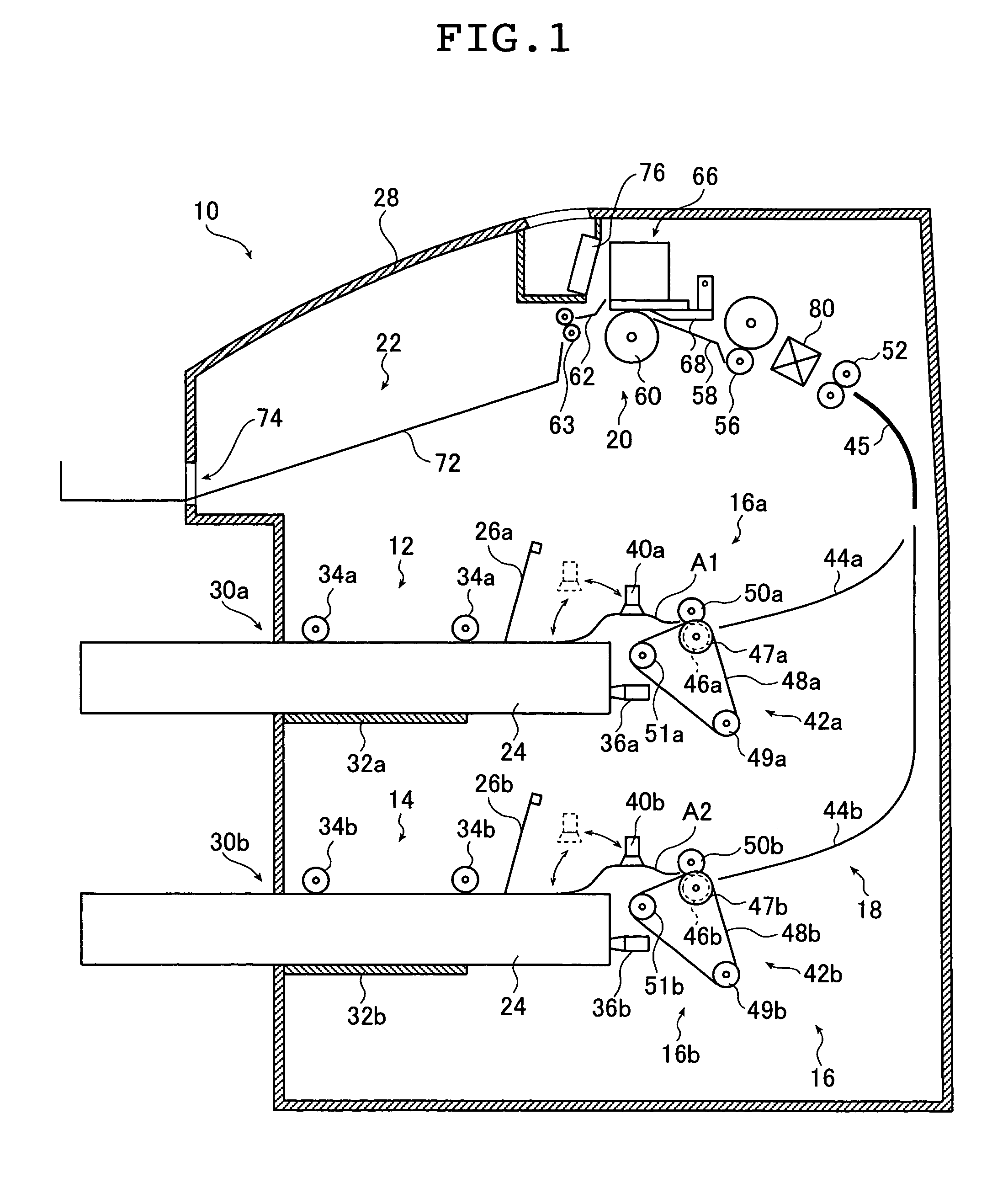
[0032]FIG. 1 is a schematic cross-sectional view showing the configuration of a thermal printer 10 according to an embodiment of the present invention.

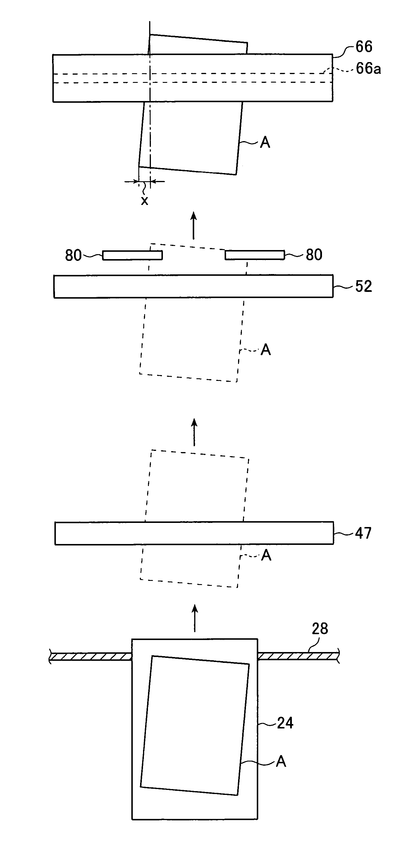
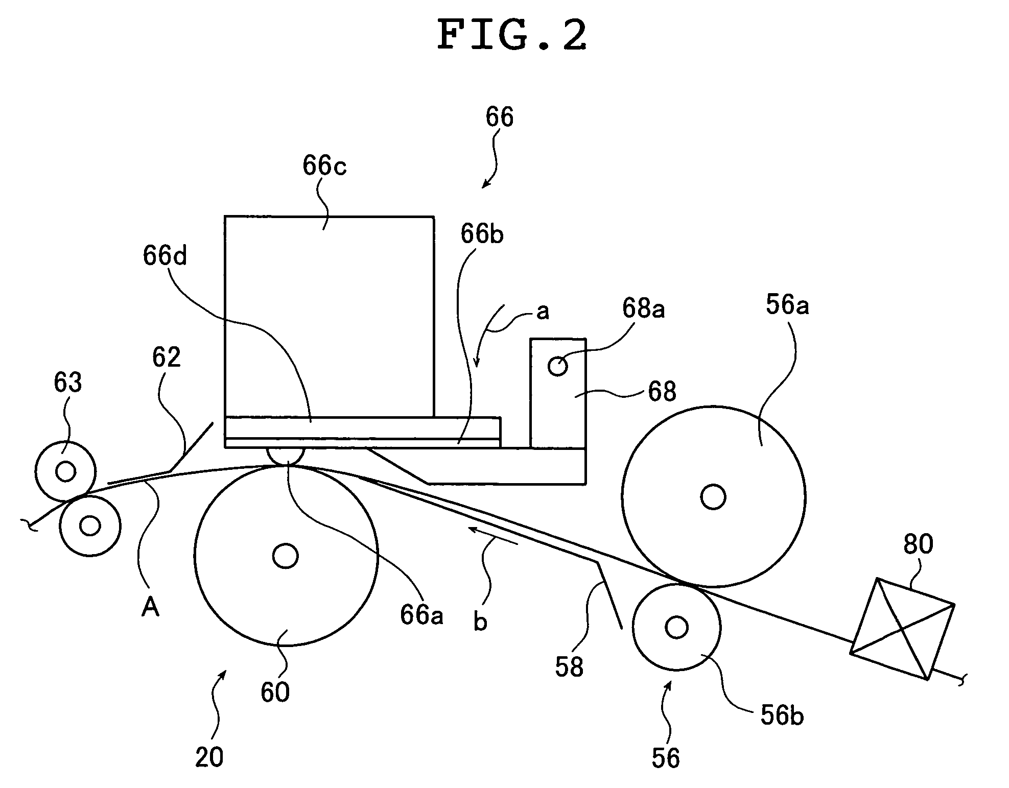
[0033]In the thermal printer 10 of the present invention, thermal recording is performed with a thermal head 66 on a thermal recording material A cut into sheets of a predetermined size (hereinafter referred to simply as a recording material A). The thermal printer 10 includes a first loading section 12 and a second loading section 14 into which magazines 24 containing the recording material A are loaded, a supply / transport section 16, a recording section 20 in which the thermal head 66 performs thermal recording on the recording material A and a discharge section 22.

[0034]As in a usual thermal printer, the illustrated thermal printer 10 performs thermal recording by heating individual ...


PUM

PropertyMeasurementUnit
sizeaaaaaaaaaa
sizeaaaaaaaaaa
sizeaaaaaaaaaa

Abstract

A thermal printer includes a thermal head which has heating elements arranged in a main scanning direction, a transport unit for transporting a thermal recording material in a sub scanning direction perpendicular to the main scanning direction and a skewing unit for skewing the thermal recording material so that its ends in the main scanning direction form an angle with respect to the sub scanning direction at a predetermined recording position. The thermal recording material that has been skewed so that its ends form the angle is supplied to the recording position, and the thermal recording on the thermal recording material is performed with the thermal head while the thermal recording material that remains skewed is transported in the sub scanning direction.

Description

[0001]The entire content of a document cited in this specification is incorporated herein by reference.BACKGROUND OF THE INVENTION[0002]The present invention belongs to a technical field of thermal printers. More specifically, the present invention relates to a thermal printer capable of preventing dirt from adhering to specified positions of a thermal head.[0003]Thermal printers have been conventionally employed to record small images such as those for ultrasonography on a thermal recording material (hereinafter referred to simply as a recording material) having a thermal recording layer formed on a support made of a film or the like.[0004]The thermal printers have advantages such as the unnecessity of wet processing and simple handling, and hence have been also employed recently to record images for the purpose of diagnoses requiring high-quality large images, as exemplified by CT (Computerized Tomography), MRI (Magnetic Resonance Imaging) and radiography.[0005]The thermal printer...

Claims


Application Information

Patent Timeline
Patent Type & Authority Patents(United States)
IPC IPC(8): B41J2/315
CPCB41J2/32
Inventor FUKUYO, MASAKAZU
Owner FUJIFILM CORP
Why Eureka
Try Eureka