Method and apparatus attenuating direct sun light while providing a view of the sky through a light tunnel in a skylight system

Inactive Publication Date: 2008-04-01
PAGEL DAN
View PDF11 Cites 21 Cited by
  • Summary
  • Abstract
  • Description
  • Claims
  • Application Information

AI Technical Summary

Benefits of technology

[0009]The tracking system can optimally control the double-sided reflective panel array by positioning the array at the frame angle. There is no need for mechanical control of a second degree of motion, due to the use of double-sided reflective panels.

Problems solved by technology

There are some problems with existing skylight attenuating mechanisms.
These mechanisms tend to degrade or eliminate a clear view of the sky.
Such a barrier also removes any clarity in seeing the sky itself.
Such mechanisms do not allow people the pleasure of directly viewing the sky.
Other attenuating mechanisms tend to require complex tracking systems, lest they become very inefficient.
The inventor has discovered that tendency toward inefficiency is due in part to the use of one sided reflective panels.
Additionally, depending on the angle of the reflective panels with respect to the sun, there may be little or no view of the sky, because the reflective panels essentially block the view in maximizing the directed sun light as in FIG. 6 of the '824 patent.

Method used


Image

  • Method and apparatus attenuating direct sun light while providing a view of the sky through a light tunnel in a skylight system
  • Method and apparatus attenuating direct sun light while providing a view of the sky through a light tunnel in a skylight system
  • Method and apparatus attenuating direct sun light while providing a view of the sky through a light tunnel in a skylight system

Examples


Embodiment Construction

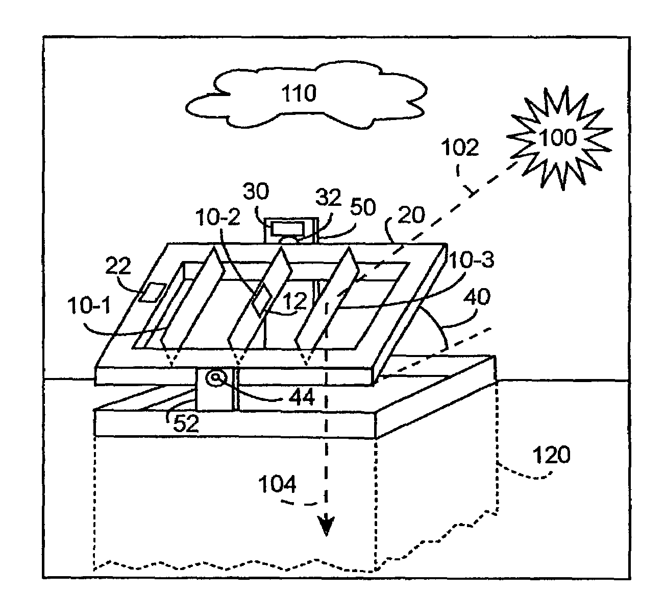
[0027]The invention includes an apparatus attenuating direct light 102 from the sun 100 at a location in the sky into a light tunnel 120 in a sky light to create a direct sun light attenuation 104 through the sky light and to create a sky view 112 through the sky light. This is illustrated in FIGS. 1A to 3.

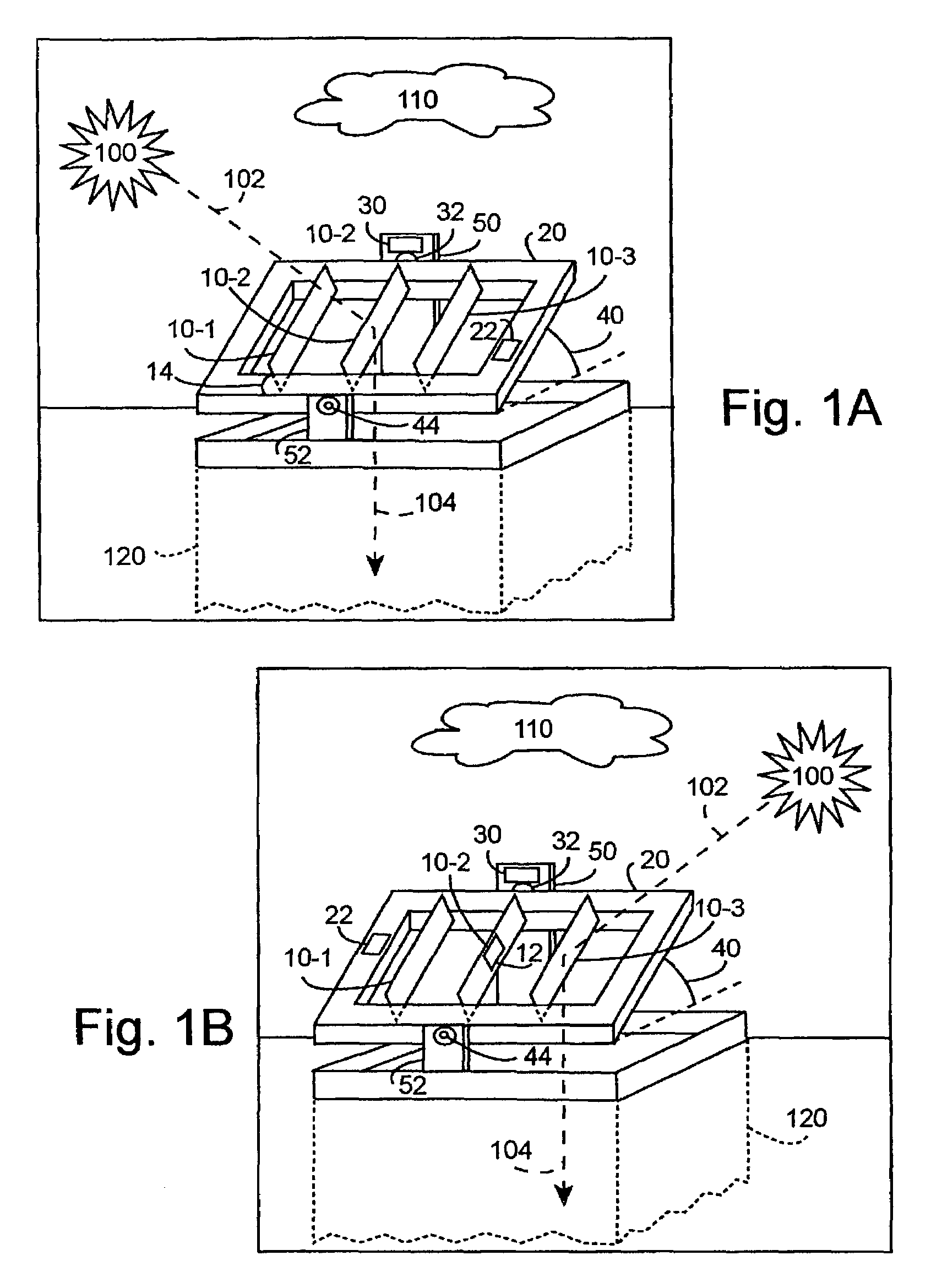
[0028]FIG. 1A illustrates an embodiment of the invention including a double-sided reflective panel array on rigid frame 20 positioned by tracking system 30, interacting with direct sunlight 102 to create the direct sunlight attenuation 104, as well as providing a view of the sky 110.

[0029]FIG. 1B illustrates the embodiment of FIG. 1A interacting with direct sunlight at a different time of day, as well as, double-sided reflective panel 10-2 further including solar cell 12.

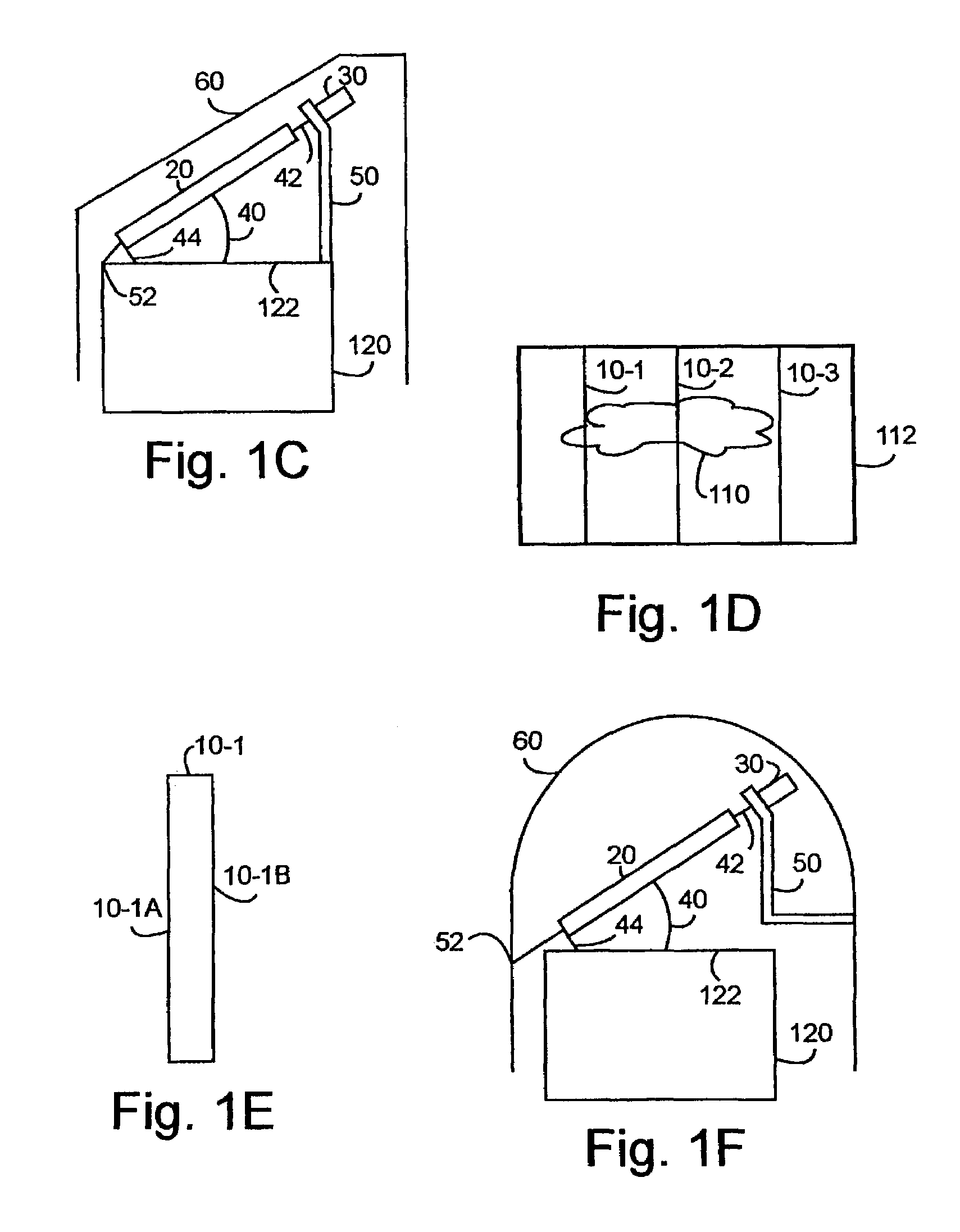
[0030]FIG. 1C illustrates a side view of the embodiment of FIGS. 1A and 1B, enclosed in an envelope 60.

[0031]FIG. 1D illustrates the sky 110 viewed through rigid frame 20 mounted, double-sided reflective panel arr...


PUM


Abstract

An array of preferably at least three double-sided reflective panels mounted on a rigid frame pivoting at a mounting angle to create a double-sided reflective panel array. A tracking system positioning the rigid frame at a frame angle, with respect to the direct sun light, and with respect to pivoting at the mounting angle, to create a rigid frame position. The double-sided reflective panel array interacting with the direct sunlight based upon the rigid frame position to create the direct sun light attenuation. The sky viewed through the rigid frame mounted, double-sided reflective panel array and through the light tunnel creates the sky view.

Description

TECHNICAL FIELD[0001]This invention relates to control of lighting through a skylight.BACKGROUND ART[0002]Skylights are well known and commonly used mechanisms increasing the lighting within buildings. A skylight includes a light tunnel connecting the interior of a building to the exterior, and some mechanism to control and / or direct sun light through the light tunnel to the interior. Controlling direct sun light through the light tunnel often comes from a need to either maximize or minimize the intensity of direct sun light in the interior.[0003]As used herein a mechanism directing sun light with respect to a light tunnel to either minimize or maximize the direct sun light in the interior will be referred to as an attenuating mechanism.[0004]There are some problems with existing skylight attenuating mechanisms. These mechanisms tend to degrade or eliminate a clear view of the sky. One well-known way to minimize direct sun light is to use translucent film as a direct light barrier. ...

Claims


Application Information

Patent Timeline
IPC IPC(8): G02B27/00E04D13/18H01L31/042E04D13/03F21S11/00F24J2/54H01L31/00
CPCE04D13/033F21S11/00H02S20/00Y02B10/12Y02E10/52F24J2/54F24S30/40H02S20/32Y02B10/10Y02E10/50
Inventor PAGEL, DAN
Owner PAGEL DAN
Why Eureka
Try Eureka