Device for monitoring tiltable flaps on aircraft wings

a technology for aircraft wings and flaps, applied in vehicle position/course/altitude control, process and machine control, instruments, etc., can solve problems such as damage to the flap structure, synchronization is no longer maintained, and flaps become twisted and jammed, so as to prevent inaccuracy and simple zero adjustment

Active Publication Date: 2008-04-08
AIRBUS OPERATIONS GMBH
View PDF12 Cites 21 Cited by
  • Summary
  • Abstract
  • Description
  • Claims
  • Application Information

AI Technical Summary

Benefits of technology

[0007]It is the object of the invention, in a simple way, to provide torsion monitoring and tilt monitoring for flaps with error localization by decentralized monitoring, wherein the monitoring prevents inaccuracies and makes possible simple zero adjustment.
[0010]In this way it may be possible to create an arrangement that may be optimal in weight, and to detect a fault in a local actuating element, as well as, by switching off the central drive, to prevent torsion or jamming of the flaps, and also to detect other incidents in the transmission, such as for example a broken shaft.
[0011]Furthermore, permanent torsion monitoring and jamming monitoring may no longer result in possible flap overloading by displacement, which may be experienced in practical application, of the so-called torque or force load limiter values at each station. The decentralized monitoring principle may provide a possibility of switching the central drive off when this fault occurs.

Problems solved by technology

There is a deficiency in that in the case of a fault of a local actuator, synchronization is no longer maintained, and the flap becomes twisted and jammed.
If the fault is not detected in time and the flap continues to be activated, this results in the destruction of the flap structure.
However, it has been shown that such an arrangement with a rod assembly or a crank arrangement is disadvantageous because their tolerances have a negative influence on measuring accuracy.
This results in the flap structures and mountings having to be designed to cope with unnecessarily large error forces.
Furthermore, in the case of flaps with a fixed rotary axis, an unnecessarily large number of additional components are required.

Method used


Image

  • Device for monitoring tiltable flaps on aircraft wings
  • Device for monitoring tiltable flaps on aircraft wings
  • Device for monitoring tiltable flaps on aircraft wings

Examples


Embodiment Construction

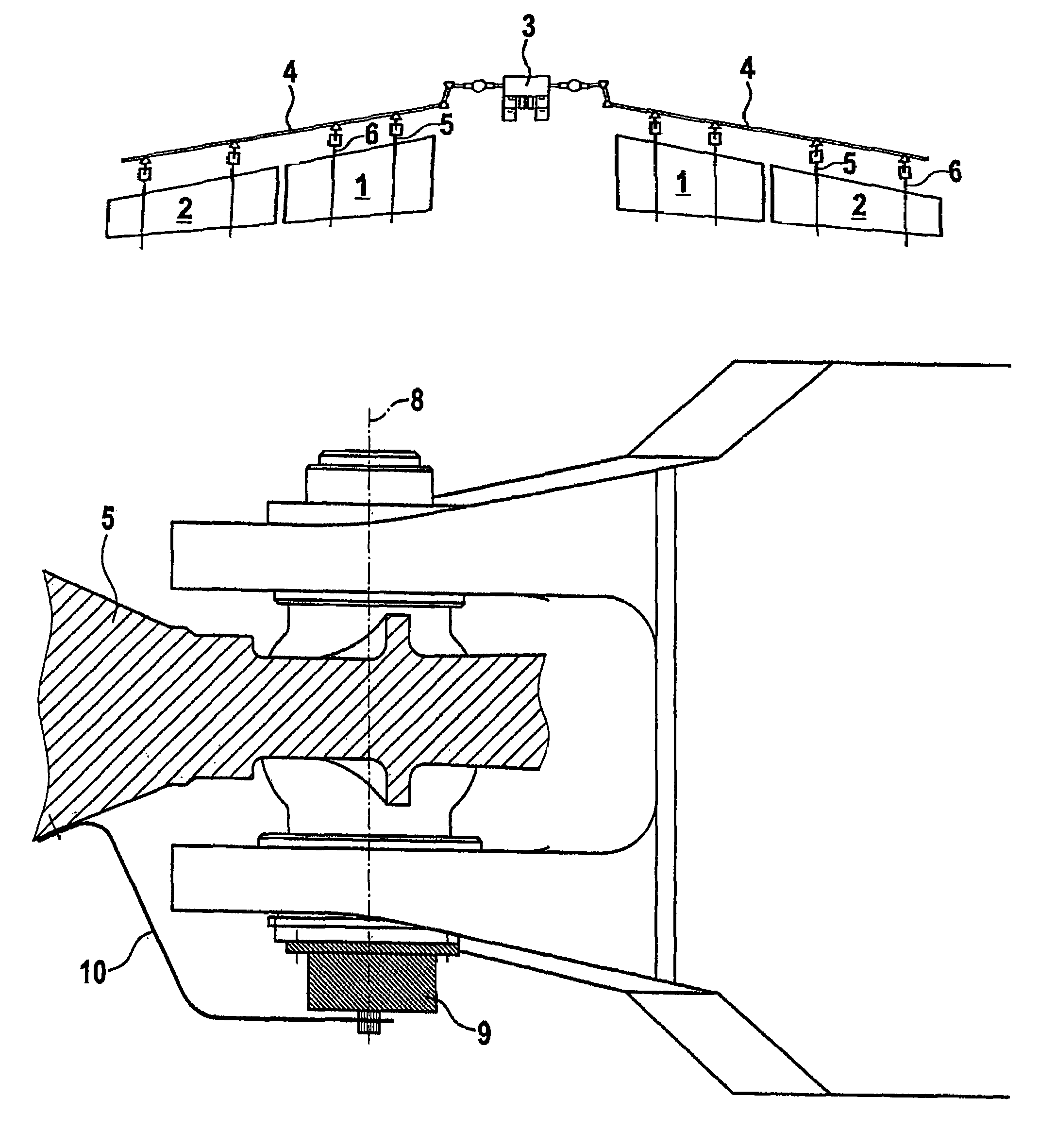
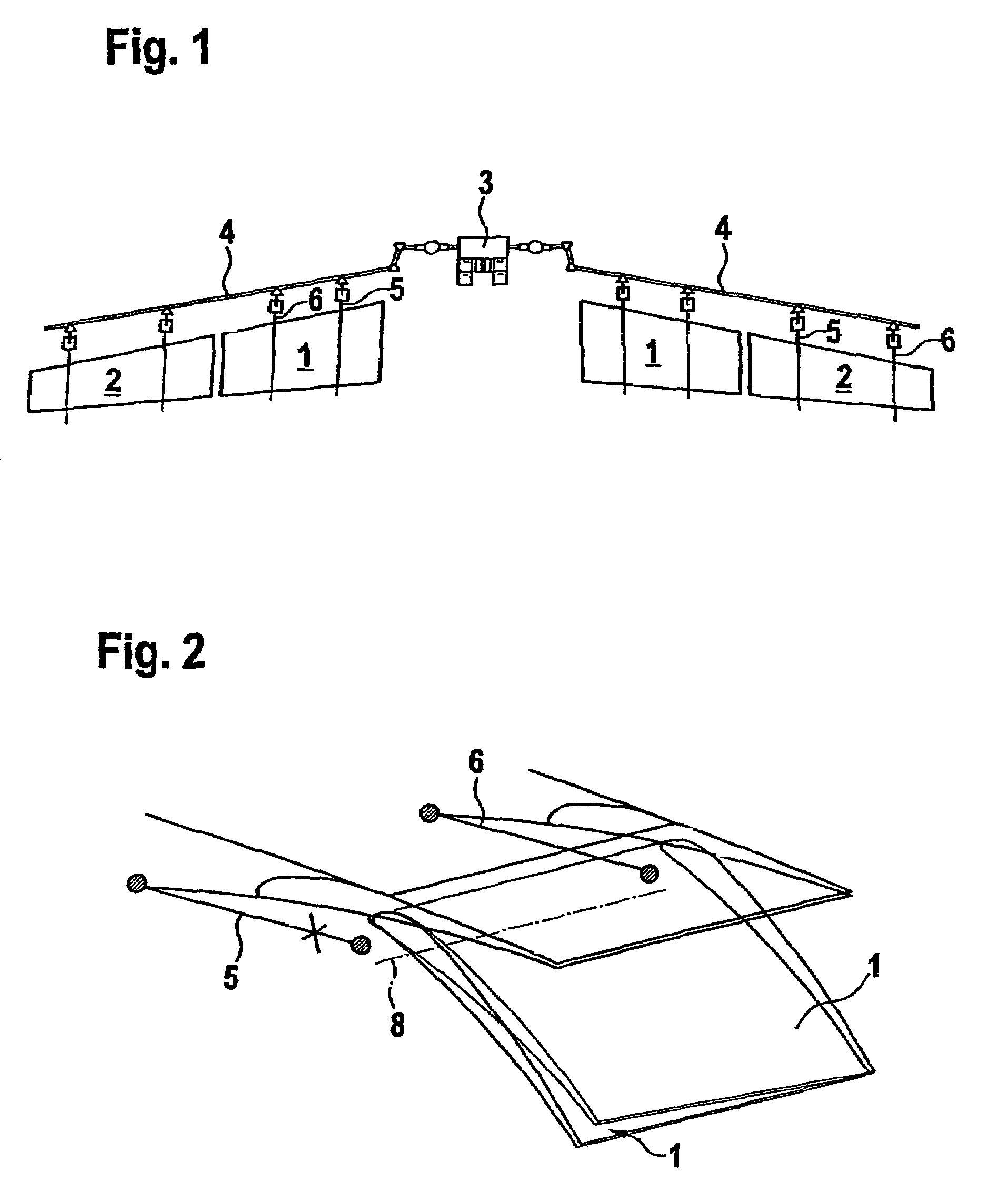
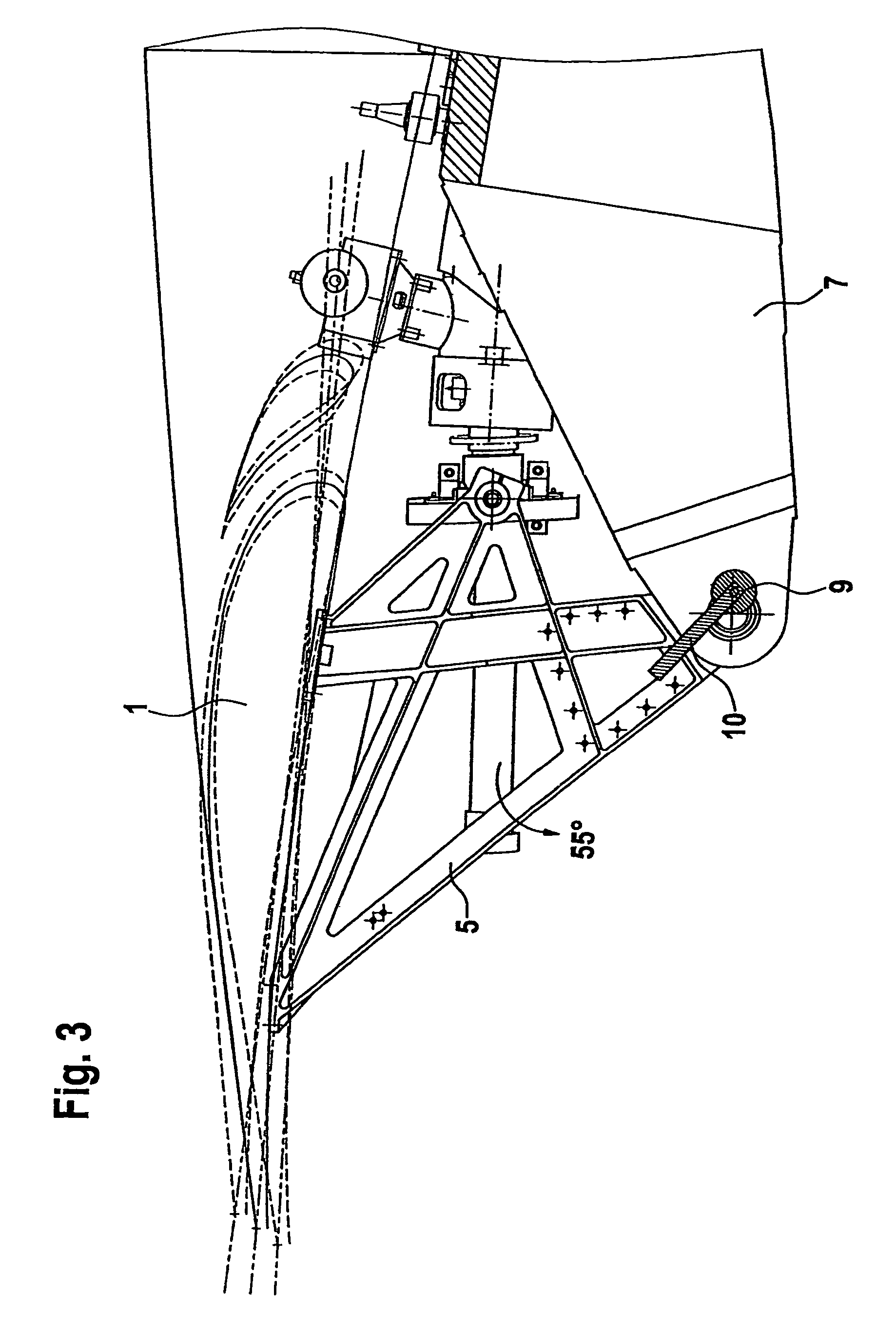
[0023]In the arrangement shown, in each case two landing flaps 1 and 2 are arranged on each wing side and are adjustable by way of a central drive unit 3 and shafting 4. In this arrangement each flap 1, 2 is held by two actuating elements 5, 6 by which the flap is tiltably adjustable. Usually the flaps 1, 2 are held by the actuating elements 5, 6 and the guide 7.

[0024]Each flap 1, 2 comprises a fixed rotary axis 8 and is tilted by way of the associated actuating element 5, 6. In each case rotary sensors 9 are associated precisely with the pivot of the respective flap 1, 2. For accomplishing direct angle transmission of the flap tilt to the sensor rotation a spring band 10 is arranged between the rotary sensor 9 and the actuating element 5, 6. This spring band 10 is a spring steel band of flat expansion in the direction of rotation. In this way, good rigidity in the direction of rotation for good measuring accuracy is achieved while at the same time providing the necessary lateral so...


PUM


Abstract

A device for monitoring tiltable flaps on aircraft wings including rotary sensors at the rotary axis of the flap and associated with each actuating element. A rotation sensor is connected to the actuating elements by a spring band. The band is a coupled for angle transmission and the band is connected at a distance from the rotary axis. The spring band is stiff in the direction of rotation, while in the lateral direction, for the purpose of compensating for transverse movements of the actuating elements, the spring band is soft. For each flap, the signals of the rotary sensors, at decentralized monitoring devices to locate errors, are transmitted to an evaluation unit.

Description

[0001]This application claims the benefit of the filing date of German Patent Application No. 10 2004 063 018.6 filed Dec. 22, 2004, the disclosure of which is hereby incorporated herein by reference.FIELD OF THE INVENTION[0002]The invention relates to a device for monitoring adjustable flaps, such as landing flaps, on aircraft wings by way of rotary sensors connector to determine incorrect positions or faulty drives by connection to an evaluation unit, wherein the flaps are adjustable by central drive units as well as by a shafting, and each flap is held and adjustable by way of several associated local actuating elements.TECHNOLOGICAL BACKGROUND[0003]In known arrangements of landing flaps, operable by way of a central drive unit with a shafting, a plurality of landing flaps are activated. Local actuating elements having the form of spindles or crank mechanisms hold and tilt the individual flap. Normally, two synchronously operating local actuating devices are arranged.[0004]There ...

Claims


Application Information

Patent Timeline
Patent Type & Authority Patents(United States)
IPC IPC(8): G05D1/00
CPCB64D45/0005B64D2045/001
Inventor RICHTER, MARTINLANG, DIETER
Owner AIRBUS OPERATIONS GMBH
Why Eureka
Try Eureka