

Lens-barrier device for camera
a technology of a lens and a shield, which is applied in the field of lens shield devices for cameras, can solve the problems of reducing the degree of freedom of camera design and the large size of the camera body, and achieve the effect of ensuring the protection of the lens
- Summary
- Abstract
- Description
- Claims
- Application Information
AI Technical Summary
Benefits of technology
Problems solved by technology
Method used
Image

Examples
Embodiment Construction
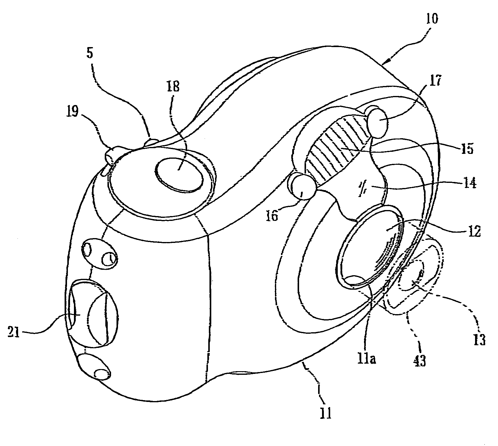
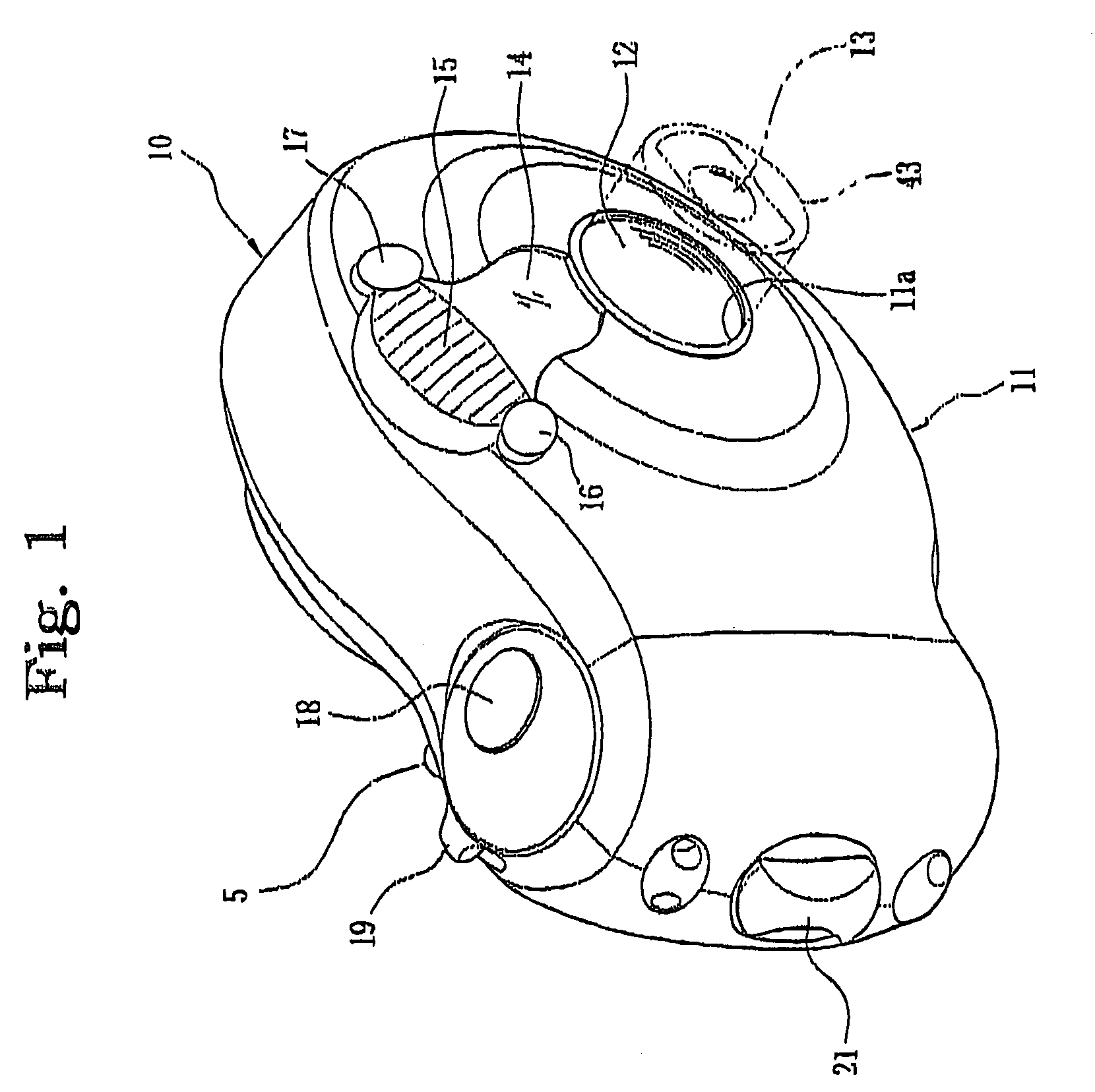
[0017]Referring to the accompanying drawings in detail, and in particular, to FIG. 1 schematically showing a camera equipped with a lens-barrier device according to an embodiment of the present invention, a camera 10 has an overall rounded body that is covered by a front cover 11 with a circular ingress / egress aperture 11a formed at its center. The front cover 11 is provided with the circular ingress / egress aperture 11a formed at its center, a finder window 14 formed above the circular ingress / egress aperture 11a, a diffusion plate 15 forming a part of a built-in electronic flash (not shown), and windows 16 and 17 forming a part of an automatic focusing device which are disposed on opposite sides of the diffusion plate 15. The camera 10 has an inner lens barrier 12 installed behind the front cover 11 and a zoom lens 13 including at least a movable lens barrel 43 which is disposed behind the inner lens barrier 12. The lens barrier 12 remains closing the circular ingress / egress apertu...
PUM
 Abstract
Description
Claims
Application Information