Hydraulic unit for industrial trucks

a technology for industrial trucks and hydraulic units, applied in the direction of pressure lubrication, cartridge filters, lift valves, etc., can solve the problems of a large number of individual components, possible leakage, and the drawbacks of reflux filters of this typ

Active Publication Date: 2008-04-08
JUNGHEINRICH AG
View PDF81 Cites 25 Cited by
  • Summary
  • Abstract
  • Description
  • Claims
  • Application Information

AI Technical Summary

Benefits of technology

[0009]A further advantage is that it is unnecessary to disconnect the reflux hose for a filter change. There is merely a need to unscrew the tank lid from a threaded socket of the tank in order to remove the filtering element. If there is a leak in the area of the reflux hose, the hydraulic medium enters the tank and does not get into the surroundings. Merely a simple O-ring gasket is required to achieve a seal between the tank and filter.

Problems solved by technology

However, a reflux filter of this type has some drawbacks.
Possible leaks result because of the externally located couplings of the hose between the hydraulic unit and reflux filter.
Moreover, the known reflux filter necessitates a relative large number of individual components.

Method used


Image

  • Hydraulic unit for industrial trucks
  • Hydraulic unit for industrial trucks
  • Hydraulic unit for industrial trucks

Examples


Embodiment Construction

[0017]While this invention may be embodied in many different forms, there are described in detail herein a specific preferred embodiment of the invention. This description is an exemplification of the principles of the invention and is not intended to limit the invention to the particular embodiment illustrated

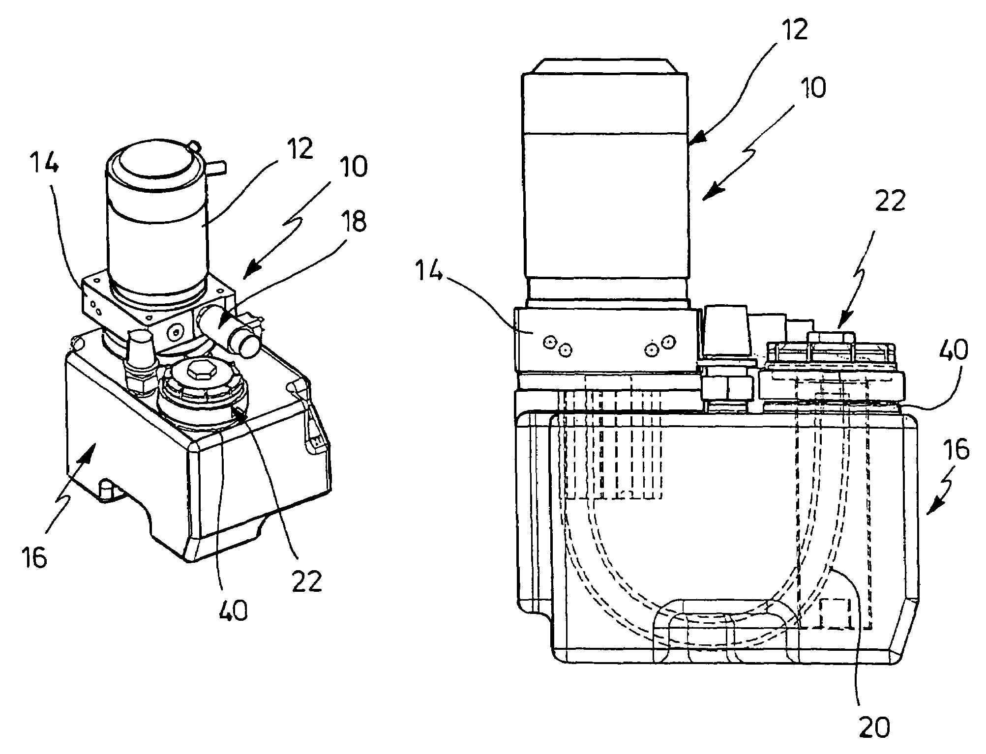
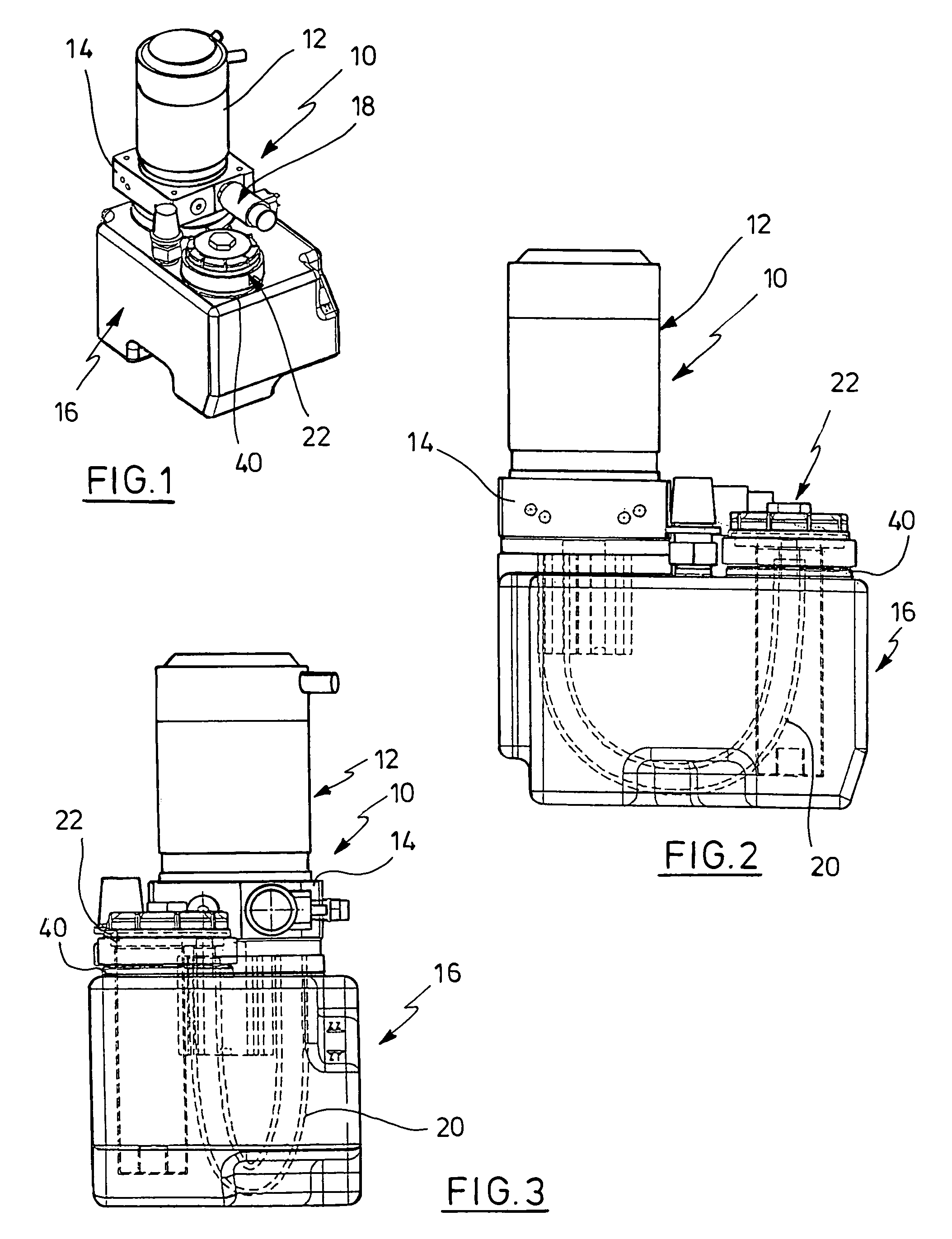
[0018]In FIGS. 1 to 3, a compact hydraulic unit 10 is shown with a motor pump unit 12, which have a common casing. The casing of the motor pump unit 12 has fastened thereto a valve casing 14 via which the motor pump unit 12 is mounted on the upper side of a hydraulic tank 16. A solenoid valve 18 is attached to the valve casing 14. The hydraulic unit described, for example, serves for actuating a lift cylinder in an industrial truck (not shown). When the motor of the motor pump unit 12 is turned on the hydraulic medium will be delivered to the lift cylinder from the tank 16. The valve assembly has provided therein a check valve which prevents the hydraulic medium from flowing b...


PUM

PropertyMeasurementUnit
areaaaaaaaaaaa
plasticaaaaaaaaaa
diameteraaaaaaaaaa

Abstract

A hydraulic unit for industrial trucks, comprising a motor pump unit which is directly attached to a tank, a reflux filter which has an elongate filter casing for a filtering element adapted to be introduced into the tank through an opening, a hose coupling, and an outlet opening, wherein the filtering element is disposed in the flow path between the hose coupling and the outlet opening, a reflux hose between the motor pump unit and the hose coupling, and a closure for the reflux filter, wherein the reflux hose extends within the tank and the hose coupling is disposed within the tank.

Description

CROSS-REFERENCE TO RELATED APPLICATIONS[0001]Not applicable.STATEMENT REGARDING FEDERALLY SPONSORED RESEARCH[0002]Not applicable.BACKGROUND OF THE INVENTION[0003]Industrial trucks are provided with a hydraulic unit to lift loads by the use of a load-carrying means. The unit comprises a driving motor, mostly an electric motor, and a pump driven by the motor as well as a valve assembly. In the simplest case, an easy-action lift cylinder is actuated with a check valve being responsible for holding the load whereas the load is lowered by releasing a return path to the tank from the valve assembly, e.g. via the unblockable check valve.[0004]It has become known already to combine the motor, pump, and valve assembly as a unit within a common casing and to place the casing directly onto a hydraulic tank from which the pump draws in a hydraulic medium. Further, it has been known to feed the flow-back medium not straight to the tank, but route it through a so-called reflux filter during the l...

Claims


Application Information

Patent Timeline
Patent Type & Authority Patents(United States)
IPC IPC(8): B01D35/027F01M11/03B66F9/22F04B23/02F15B1/26F15B21/041
CPCB01D35/0276B66F9/22F04B23/028F15B1/26F15B21/041Y10T137/8085Y10T137/794Y10T137/8013
Inventor BECKER, MARION
Owner JUNGHEINRICH AG
Why Eureka
Try Eureka