Remote controlled intelligent lighting system

a remote control and intelligent lighting technology, applied in the direction of electric controllers, ignition automatic control, instruments, etc., can solve the problems of manual setting of devices, physical size, and high cost of manual setting

Inactive Publication Date: 2008-04-08
SID ALBERTO
View PDF9 Cites 80 Cited by
  • Summary
  • Abstract
  • Description
  • Claims
  • Application Information

AI Technical Summary

Benefits of technology

[0009]A further object of the invention is to provide a method for using a user-actuable remote controller to remotely set the address of one or any number of installed lighting devices, to avoid the use of multiple switches on each one of the lighting devices.
[0010]Another object of the invention is to provide a method for setting a single or multiple groups of lights to any desired level of light intensity, thus creating, storing and later recalling single or multiple scenes in order to create different illuminating effects.
[0018]One embodiment of the present invention includes a remote control unit, which generates an infrared or radio frequency encoded signal in a specific format. It includes a digital display (such as a vacuum fluorescent tube, a liquid crystal or a light emitting diode type) to visually communicate with the person operating the system. A microprocessor generates the proper encoded signal and error correction protocol. By means of a keyboard or keypad the user is able to set the address of each one of the lighting devices. This system also allows you to create, store and latter recall scenes; to access individually each one of the addressable lighting devices of the system; and, to globally access all the devices present on the system and set any desired intensity level.
[0020]It also includes the capability of sending a global signal to simultaneously access all the lighting devices, regardless of their unique address. This feature is useful if the person operating the system desires to turn all the lights on to full intensity—such as in the case of a fire emergency—or turn all the lighting devices off, or to any desired light intensity, without the need of creating a special scene to define this specific global state, and thus eliminating the need of sequentially transmitting the information to each one of the lighting devices. This remote control also includes the capability of detecting and informing the person operating the system of a low battery condition, which may render the remote control unusable.

Problems solved by technology

A drawback to these known lighting devices is that the addresses of the devices must be set manually using dual in-line package (DIP) switches, binary, hex rotary switches, or thumbwheel switches.
While any these types of switches are widely used, they are usually expensive, physically big, cumbersome and difficult to set.
When the lighting devices have been mounted on ceilings, high walls, fly roads or any other location many feet above the floor, this can present a problem.
When these lighting devices are mounted in recessed locations or fixed spots, this difficulty is increased.
The address switches may also be obstructed by other objects as well, such as the mounting bracket for the lighting device, further increasing the difficulty of changing the address of the device.
In addition, while there are many different stand alone dimmers to be used with plug-in lamps, for temporarily or permanently connected lighting devices, none offers a self contained unit, containing both the remotely actuated dimmer and the lighting device.
This is useful for an installation where many lights need to be adjusted, but it is too complicated a device when only a few single units need to be adjusted.

Method used


Image

  • Remote controlled intelligent lighting system
  • Remote controlled intelligent lighting system
  • Remote controlled intelligent lighting system

Examples


Embodiment Construction

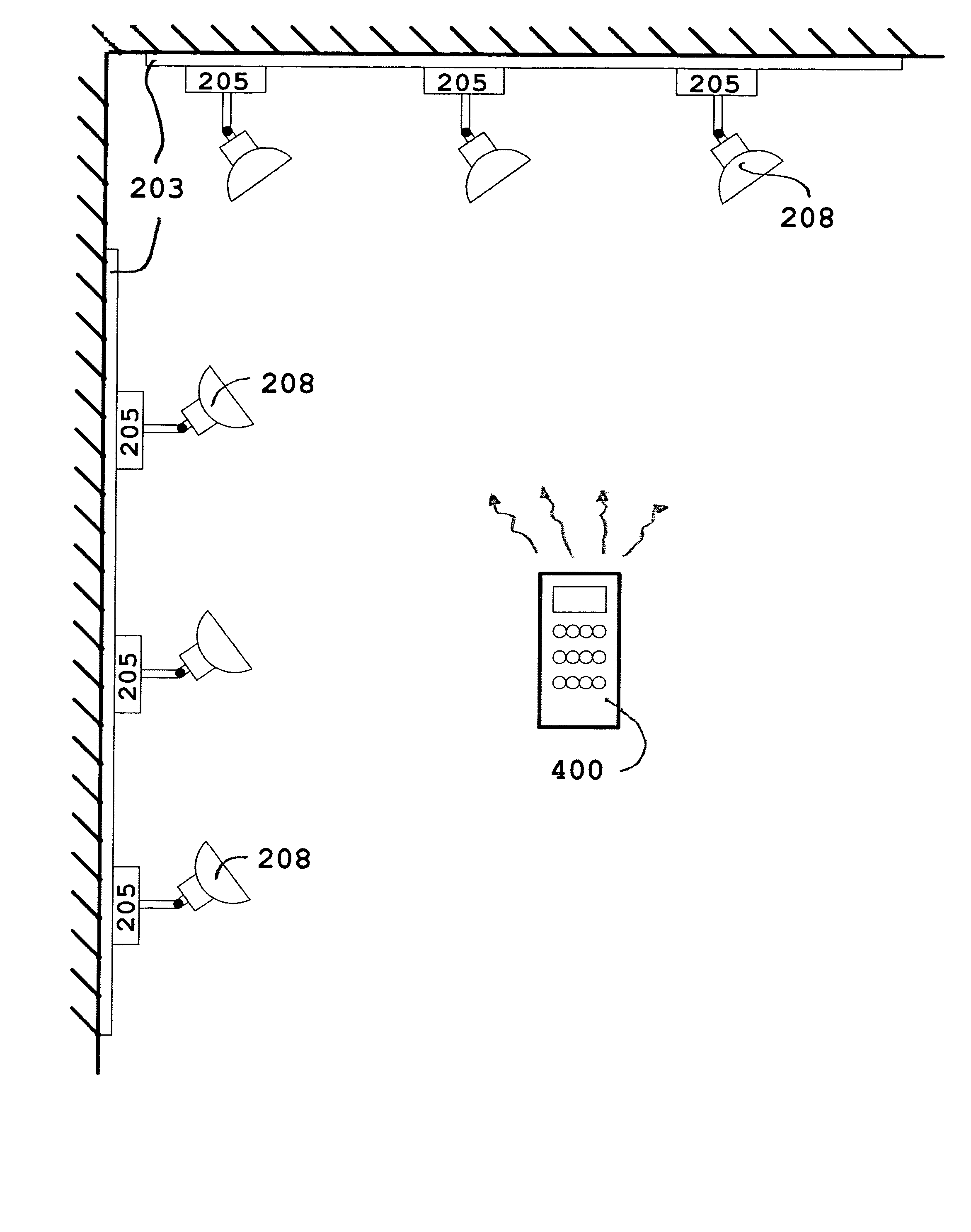
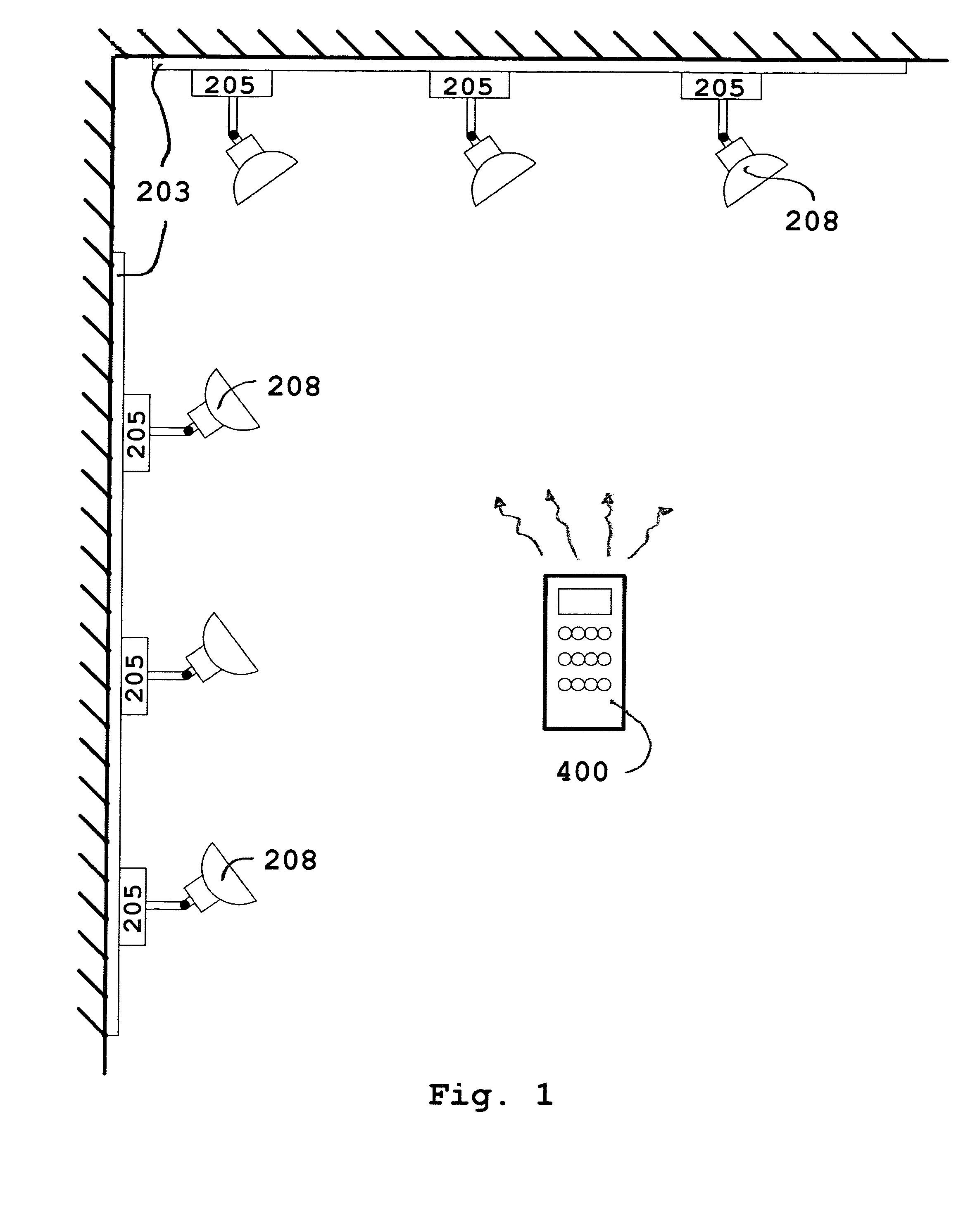
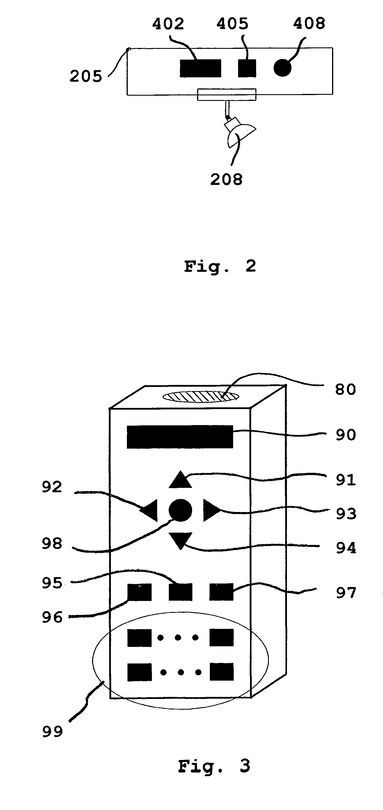
[0039]As represented in FIG. 1, the layout of a control system, of the type used in the invention, comprises an infrared or radio frequency generating remote control device 400 used to sequentially transmit data to all or any one of the addressable lighting devices 205, each one containing a light source 208 used to illuminate an area. These devices 205 are to be mounted in electrical boxes in walls or ceilings. Another variation is that they can be mounted in existing track lighting systems 203 manufactured by a variety of manufacturers such as Lutron, Lightolier, Leviton, and many others, effectively converting a simple lighting system into a sophisticated, innovative and individually addressable system which can now enable the user to create special effects by adjusting different levels of intensity of each one of the lights in the same lighting track. A particular advantage of this retrofit installation is that existing wiring can effectively be used, avoiding the expense of run...


PUM


Abstract

An addressable lighting device and control system uses a user-actuable infrared or radio frequency operated remote control(s) to selectively or collectively generate an electronic address for the addressable lighting device on which the device will respond to all future signals from the remote control corresponding to that electronic address. The addressable lighting device has a programming mode for setting the address and a working mode for receiving control signals on the set address and correspondingly setting the desired intensity level of light. The addressable device may have the address set and changed locally (manually) or remotely using the remote control to switch modes, thereby avoiding the problems, expenses and mistakes associated with using dual in-line package (DIP) switches, binary, hex rotary switches, or thumbwheel switches normally used to set each one of the system's unit's unique address.

Description

FIELD OF THE INVENTION[0001]The present invention relates generally to the field of control systems for lighting devices and, in particular, to a new and useful electronically addressable lighting device and a user-actuable infrared (IR) or radio frequency (RF) protocol addressing system for programming and recalling different states and power intensity levels of one or more electrical devices in one or more zones for the creation of one or more lighting scenes.BACKGROUND OF THE INVENTION[0002]In many lighting applications, there is a single light or plurality of lights that needs to be controlled individually (one unit at a time) or in groups (several units “grouped” together) or all the lights simultaneously. Among the installations where there is such a requirement are residential track lighting containing a plurality of individual light heads attached to a powered metal track mounted in ceilings and or walls; ceiling lighting having a plurality of lights such as factory and offi...

Claims


Application Information

Patent Timeline
Patent Type & Authority Patents(United States)
IPC IPC(8): H04Q5/22H05B37/02
CPCH05B37/0272Y02B20/48Y02B20/40H05B47/195
Inventor SID, ALBERTO
Owner SID ALBERTO
Why Eureka
Try Eureka