
Vented and ducted sub-rack support member

a sub-rack support and sub-rack technology, applied in the direction of cooling/ventilation/heating modifications, electrical apparatus casings/cabinets/drawers, electrical apparatus, etc., can solve the problems of short component life, unexpected failure, and insufficient cooling air flow depicted in fig. 1b, so as to increase the air flow velocity, increase the air flow, and increase the air flow. effect of flow

Active Publication Date: 2008-04-08
NATIONAL INSTRUMENTS
View PDF33 Cites 65 Cited by
  • Summary
  • Abstract
  • Description
  • Claims
  • Application Information

AI Technical Summary

Benefits of technology

The patent describes a chassis for plug-in modules that has a vented and ducted sub-rack support member to increase air flow to heat producing components. The air flow is directed through vents in the support member and upper deflectors to provide additional cooling to components on plug-in cards near the backplane. Fans force air into or out of the chassis to provide air flow within the chassis. The design of the support member and upper deflectors allows for adjustable air flow and cooling capabilities for specific parts of the chassis. Vent blockers can be used to selectively block certain vents and allow for different configurations of open vents. The technical effects of the invention include improved cooling efficiency and better air flow control for plug-in modules.

Problems solved by technology

However, due to the compact design of these modules, parts of the module may be difficult to cool sufficiently.
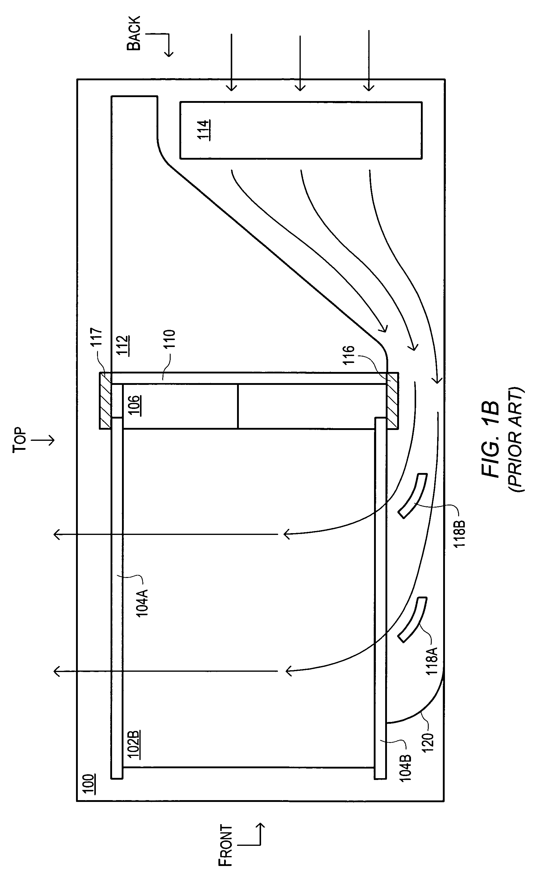
However, the air flow depicted in FIG. 1B may be ineffective in providing sufficient cooling to heat producing components mounted on the front of backplane 110 or mounted near the connector end of plug-in module 102B.
The resulting excessive component temperatures may result in shorter component lives and / or unexpected failures.

Method used


Image

  • Vented and ducted sub-rack support member
  • Vented and ducted sub-rack support member
  • Vented and ducted sub-rack support member

Examples


Embodiment Construction

[0033]Vented and Ducted Sub-Rack Support Member

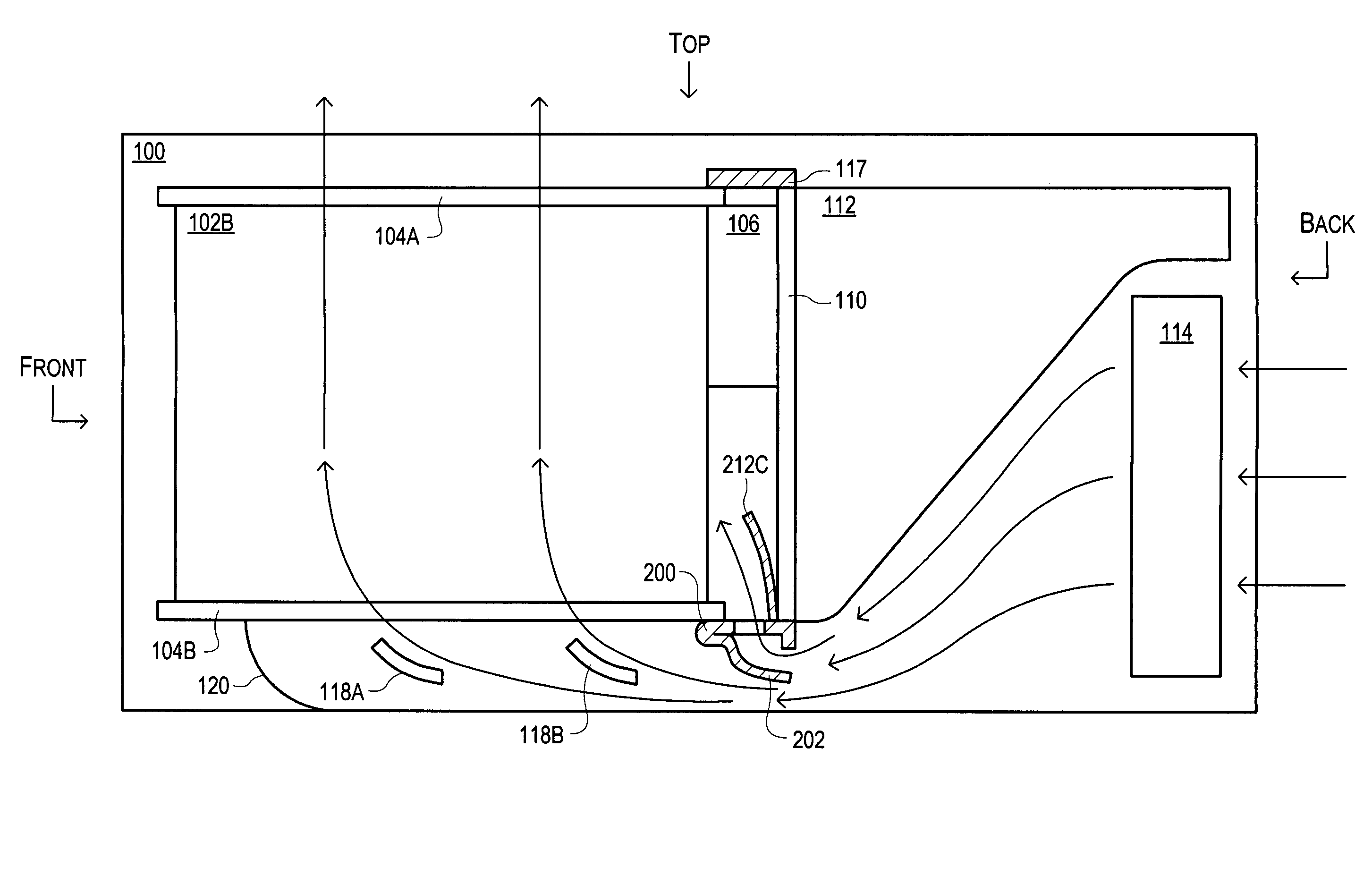
[0034]FIG. 2 illustrates one set of embodiments of an internal structure of a chassis 100 designed to receive plug-in modules, such as plug-in module 102B. The plug-in module 102B may be guided during insertion into the chassis 100 by at least guide rails 104A-B until connectors 106 make connection. Connectors 106 may comprise a pair of connectors (not shown in FIG. 2), one mounted on the plug-in card 102B and a mating connector mounted on the backplane 110. Additional circuitry 112 may be mounted behind the backplane 110 and may interact with the plug-in card 102B through the connectors 106. Backplane 110 and guide rail 104B may be coupled to vented and ducted sub-rack support member 200 (also referred to herein as support member 200). One or more fans 114 may force air into the chassis 100 and toward the support member 200 (arrows indicate typical air flow). A scoop portion 202 (also referred to herein as scoop 202, scoop 208, scoop 2...


PUM


Abstract

A chassis for plug-in modules may be provided with a vented and ducted sub-rack support member. The vented and ducted sub-rack support member may deflect a portion of the air flowing within the chassis through vents in the top surface of the vented and ducted sub-rack support member in order to increase the air flow to heat producing components mounted on the backplane above the support member. The increased air flow may increase air flow velocity and decrease the ambient temperature of the air around these components and improve the dissipation of heat from each component into the air. Air flow above the vented and ducted sub-rack support member may also be redirected by upper deflectors mounted on the support member to portions of plug-in cards adjacent to the upper deflectors and may provide additional cooling to components on the plug-in cards near the backplane.

Description

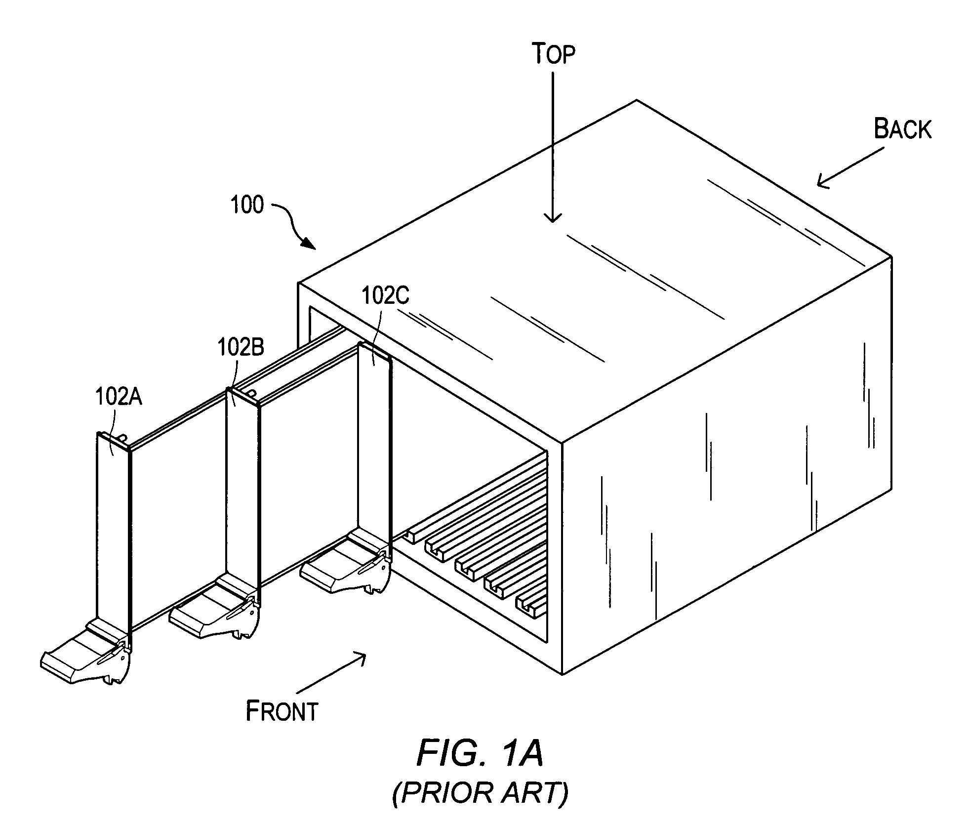
BACKGROUND OF THE INVENTION[0001]1. Field of the Invention[0002]The present invention relates generally to mechanisms for cooling heat producing components on electronic circuit boards, and more particularly, to the cooling of components by air flow generated by fans.[0003]2. Description of the Related Art[0004]Instruments for collecting data or information from an environment or unit under test may be coupled to and controlled by computer systems. Data collected by these instruments may be used to control units being tested (e.g., an overheated unit may be shutdown) or an environment (e.g., ventilation systems may be activated if a certain chemical is detected in the air). Data may also be displayed to a user for control and / or experimental purposes (e.g., to improve the design of the unit being tested). Instruments and / or computer systems may also perform various data analysis and data processing on acquired data prior to control of the unit and / or display of the data to the user....

Claims


Application Information

Patent Timeline
Patent Type & Authority Patents(United States)
IPC IPC(8): H05K7/20H05K5/00
CPCH05K7/20563
Inventor BALDWIN, JR., RICHARD G.
Owner NATIONAL INSTRUMENTS
Learn More