

Method of forming bushings between guide pins and guide pin bores
- Summary
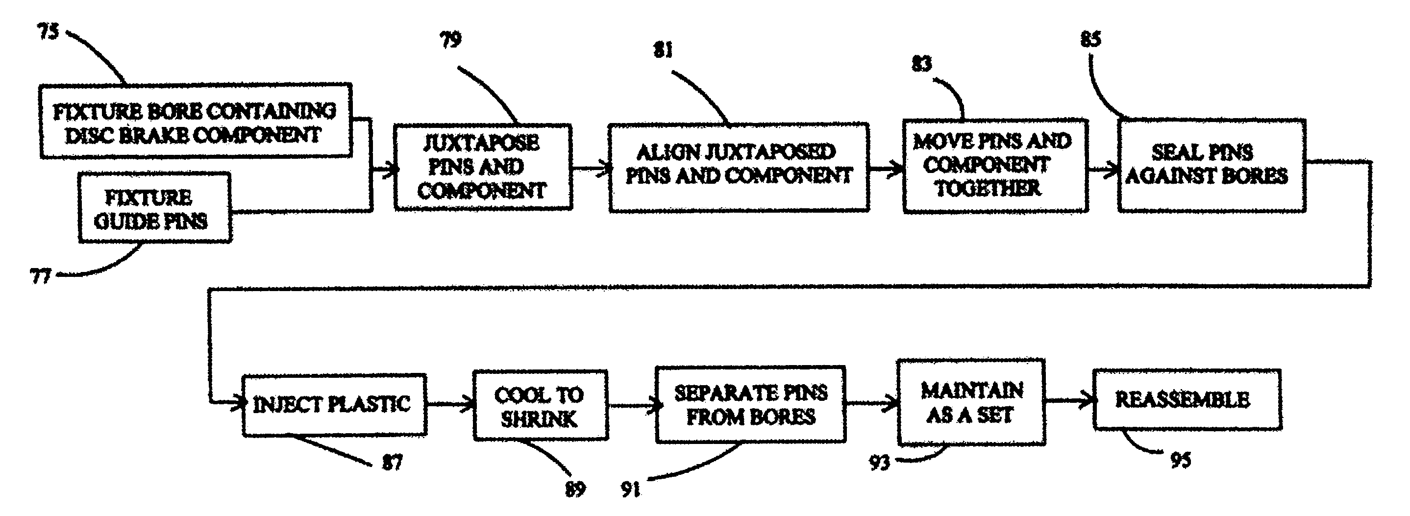
- Abstract
- Description
- Claims
- Application Information
AI Technical Summary
Benefits of technology
Problems solved by technology
Method used
Image

Examples
Embodiment Construction
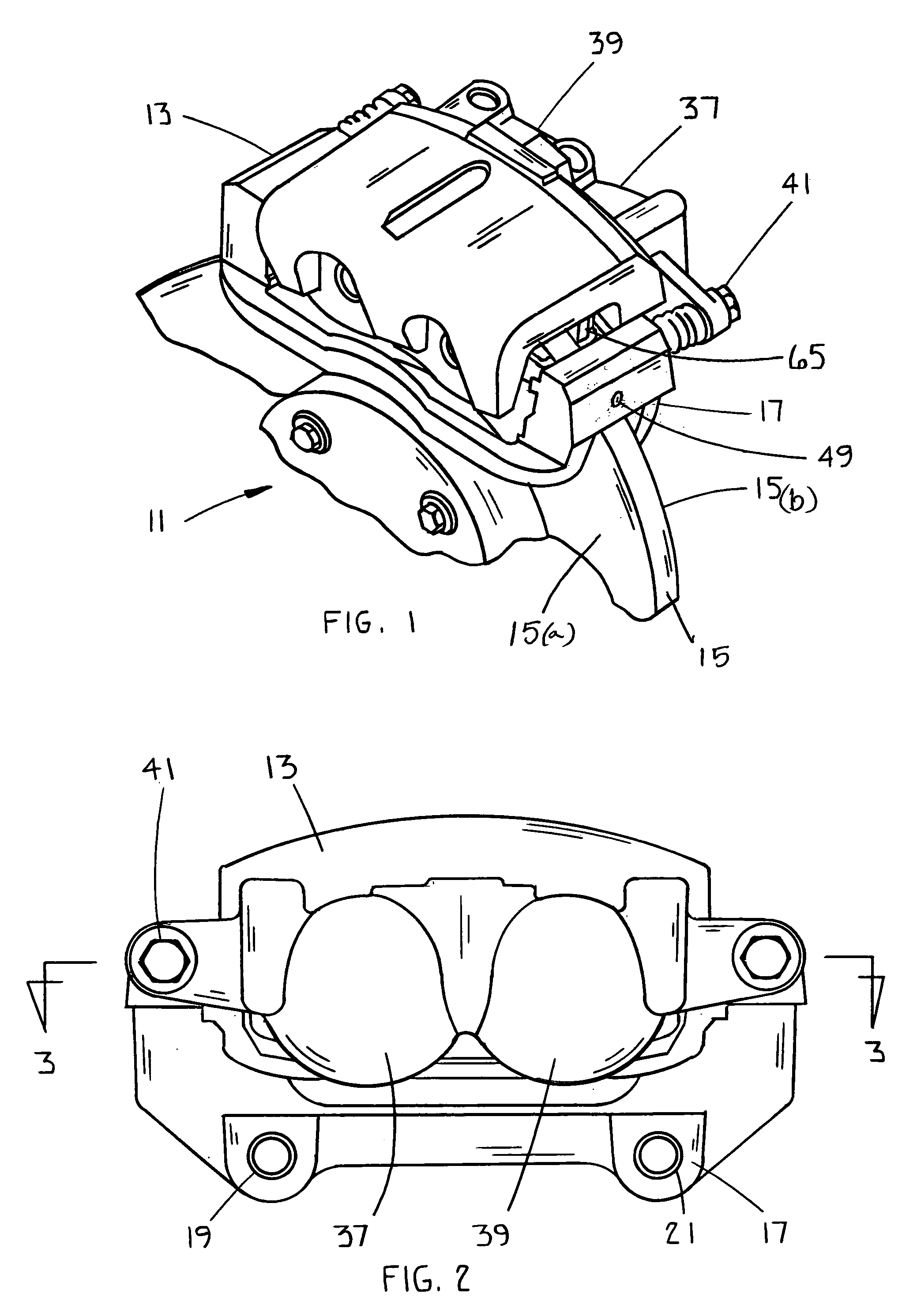
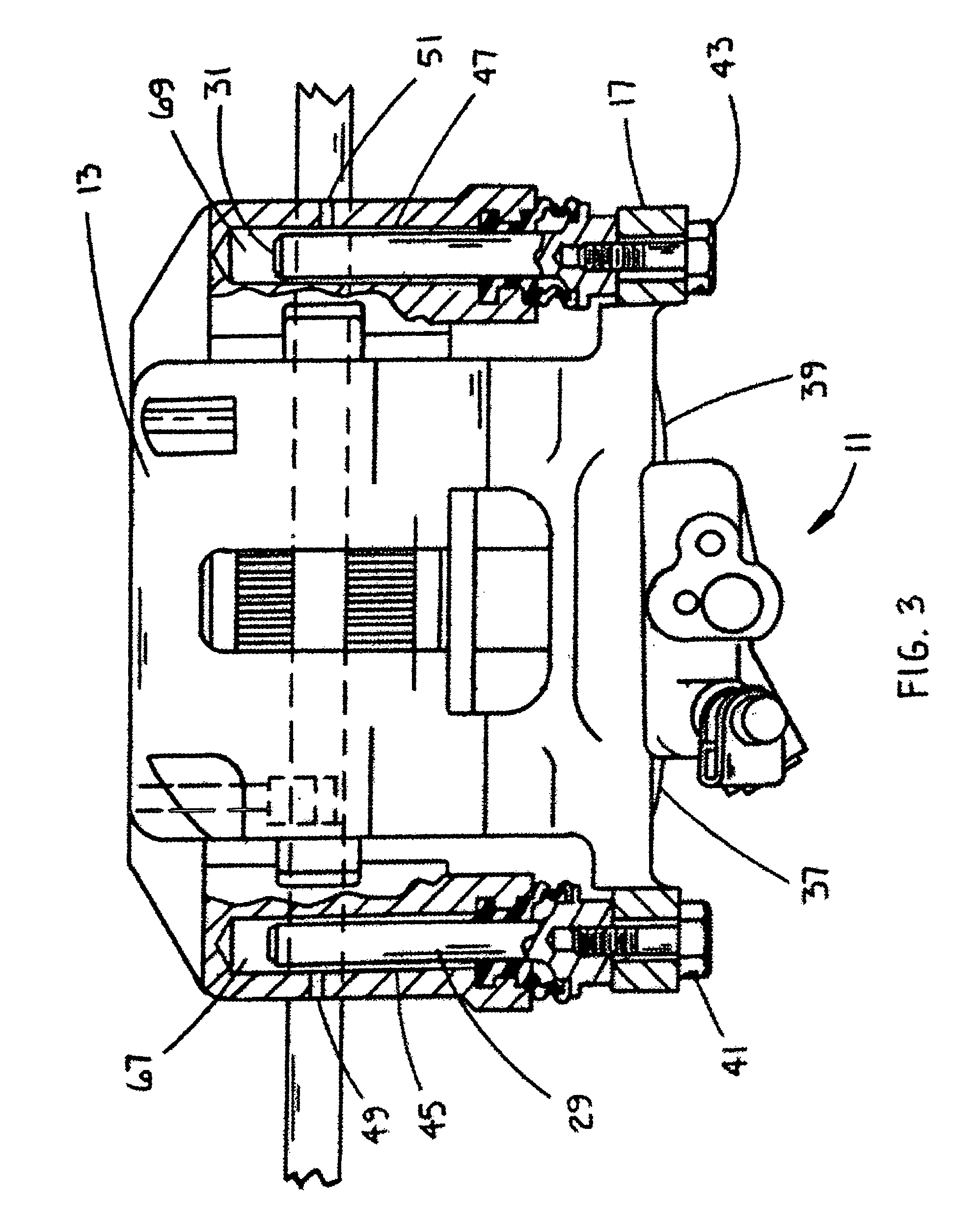
[0017]Referring now to the drawings and particularly to FIG. 1, there is shown a disc brake assembly 11 for a motor vehicle with a caliper 13 that straddling a rotor 15. A carrier or anchor bracket 17 is fixed to the vehicle by bolts passing through mounting bosses 19 and 21 (FIG. 2). The caliper 13 includes cylinders 37 and 39 for housing pistons that are moved by pressurized fluid to effect a brake application. A guide means that includes guide pins 29 and 31 are reciprocally disposed in bores 67 and 69 of caliper 13 (FIG. 3) to allow the caliper 13 to slide relative to the anchor bracket 17 when the pistons are actuated by the pressurized fluid. First friction pad 65 and a second friction pad (not visible) are aligned with and respectively directed towards opposite faces 15a and 15b of the disc 15 that are retained between the pistons and the caliper 13 and are applied to the disc 15 when the pistons are actuated.
[0018]The guide means includes cantilevered first and second cylind...
PUM
| Property | Measurement | Unit |
|---|---|---|
| Shrinkage | aaaaa | aaaaa |
Abstract
Description
Claims
Application Information