Percussion power tool

a power tool and percussion technology, applied in the field of percussion power tools, can solve the problems of inadvertent falling of the chuck off the power tool, and achieve the effects of preventing the wear of the locking member or the locking member-receiving means, good damping, and good positioning of the chuck

Inactive Publication Date: 2008-04-15
HILTI AG
View PDF16 Cites 6 Cited by
  • Summary
  • Abstract
  • Description
  • Claims
  • Application Information

AI Technical Summary

Benefits of technology

[0010]Advantageously, the output member has a receptacle for receiving the damping member. This insures an exact axial positioning of the damping member which, in turn, insures an adequate decrease of the impact energy between the output member and the chuck.
[0016]Advantageously, the damping member is formed of an elastomeric material, which permits to achieve a satisfactory reduction of the impact energy between the output member and the chuck and, thereby, a sufficient reduction of acceleration of the adjusting sleeve in the operational direction.

Problems solved by technology

The drawback of the power tool described above consists in that during operation, in particular during an idle stroke, the die impacts an axial stop of the sleeve-shaped output member, and a very large portion of the impact energy is transmitted to the adjusting sleeve by the connection member and the circlip mounted thereon.
This results in many cases in inadvertent falling of the chuck off of the power tool.

Method used


Image

  • Percussion power tool
  • Percussion power tool
  • Percussion power tool

Examples


Embodiment Construction

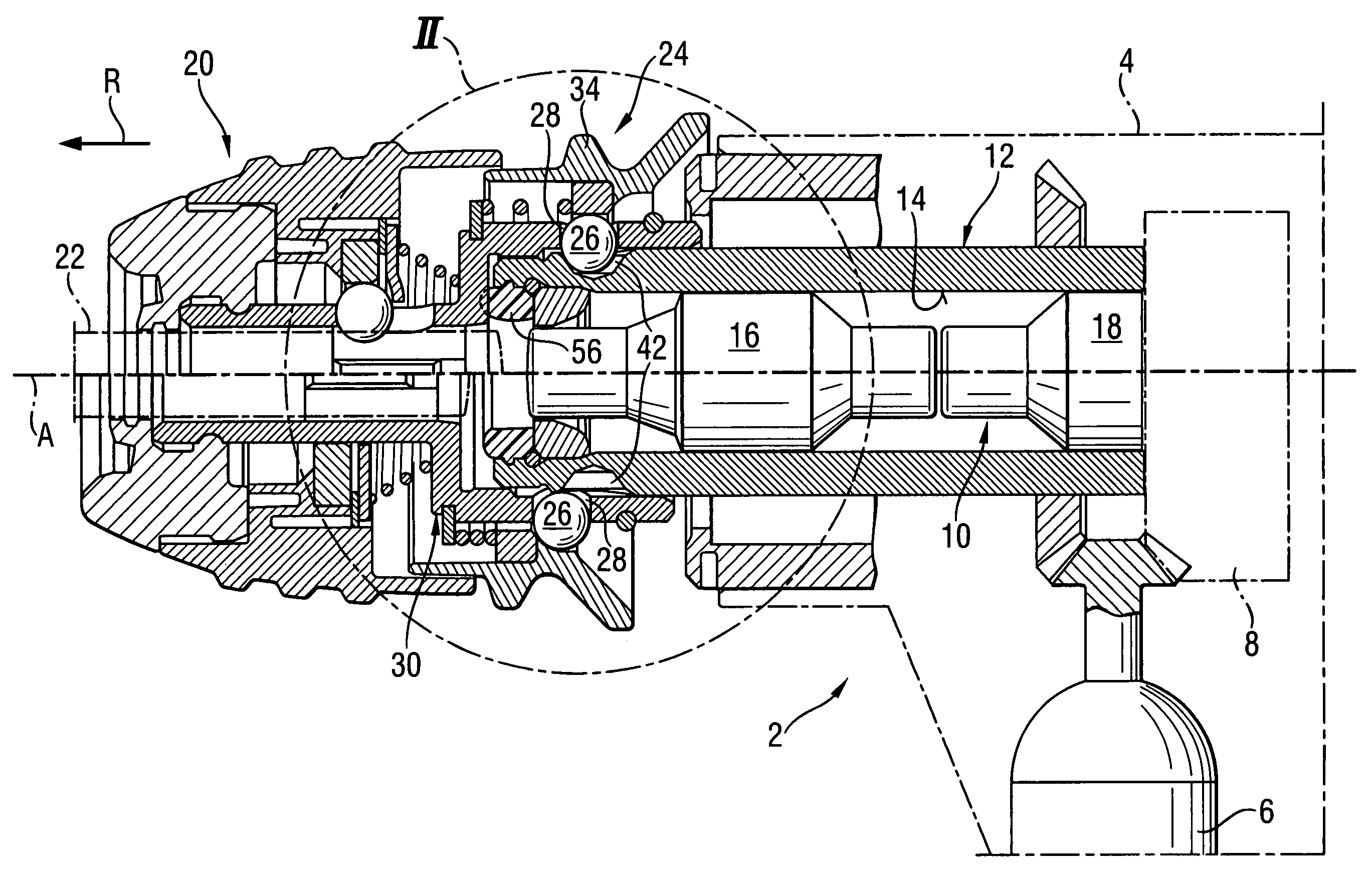
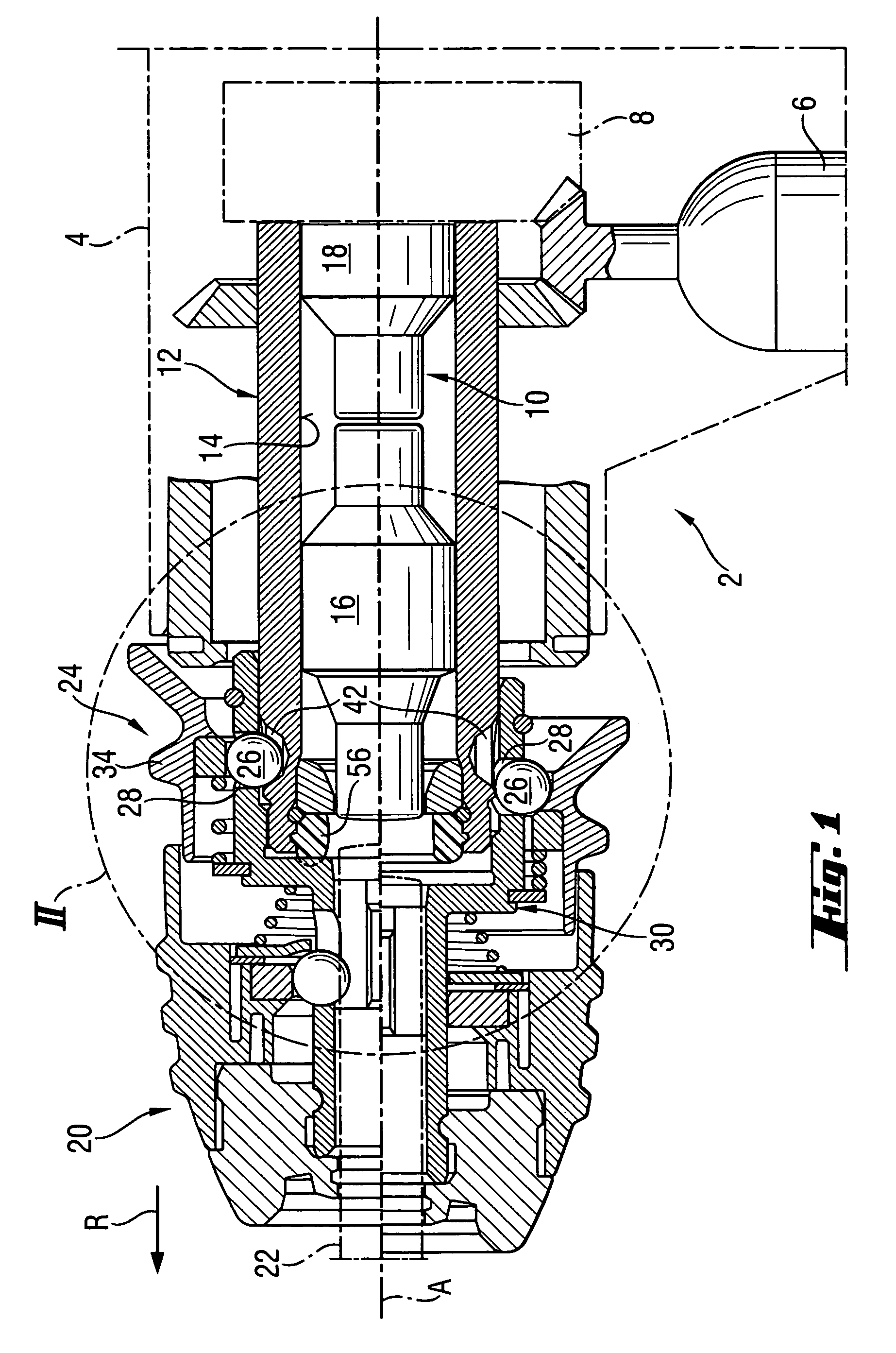
[0021]A percussion power tool 2 according to the present invention, a front portion of which is shown in FIG. 1 and which is formed as a hammer drill, includes a housing 4 in which a motor 6 is arranged. As schematically shown in FIG. 1, the motor 6 drives a driver 8 of a percussion mechanism 10 and rotates a output member 12. The output member 12 is formed as a tubular member in a longitudinal bore 14 of which a die 16 of the percussion mechanism 10 is displaceable. The die 16 is impacted by a striker 18 driven by the driver 8.

[0022]A chuck 20 for receiving a working tool 22 formed, e.g., as a drill or chisel, is mounted on the output member 12 and is releasably secured thereon with a locking mechanism 24. During an operation, the chuck 20 rotates, together with the output member 12, about a common axis A. Simultaneously, the percussion mechanism 10 impacts the working tool 22 received in the chuck 20 in the operational direction R parallel to the axis A.

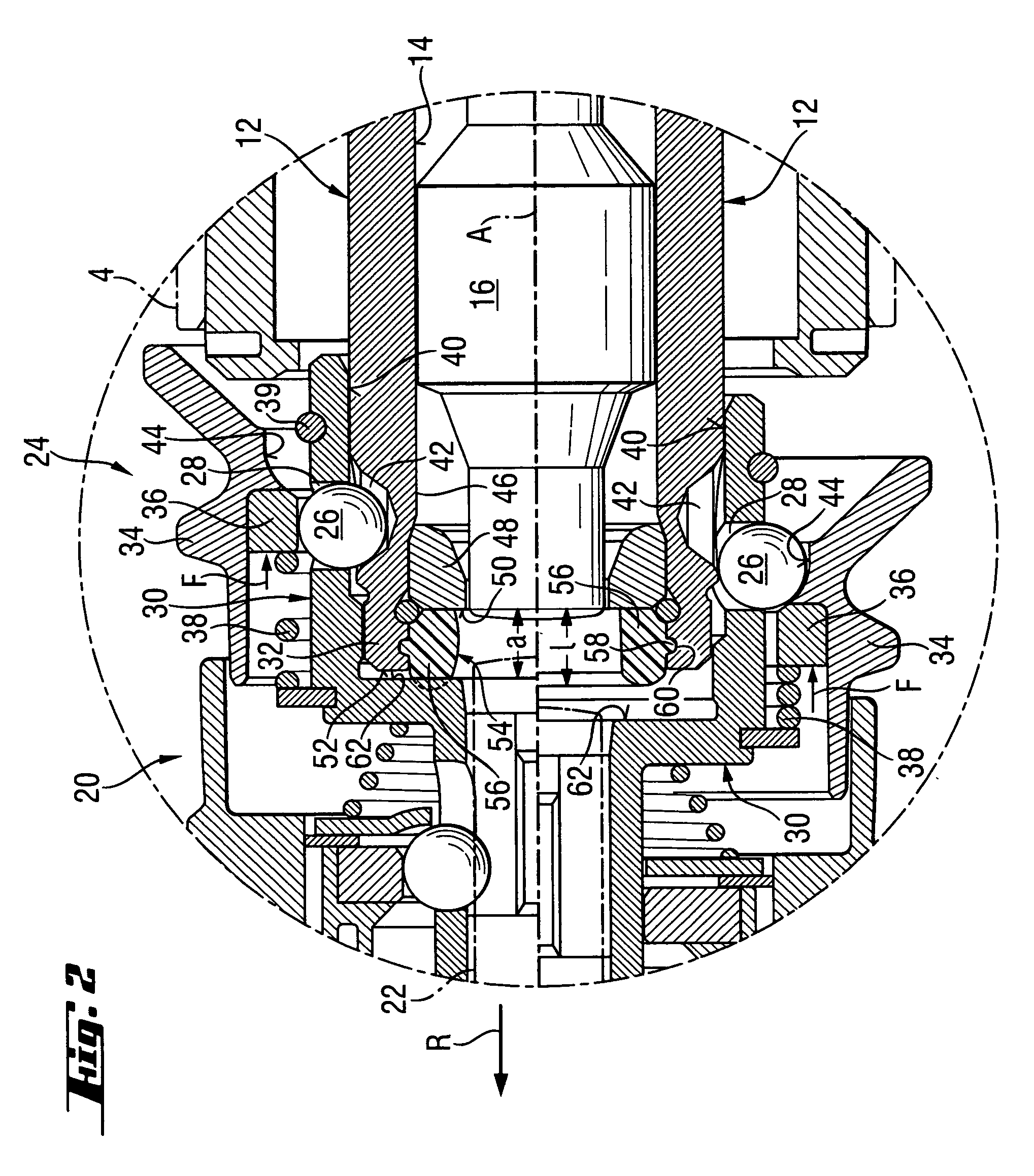
[0023]In the upper, with re...


PUM

PropertyMeasurementUnit
biasing forceaaaaaaaaaa
axial lengthaaaaaaaaaa
axial distanceaaaaaaaaaa

Abstract

A percussion power tool includes a motor (6) located in the tool-housing (4) for driving the output member (12) and the percussion mechanism (10), a chuck (20) for receiving a working tool (22), a locking mechanism (24) for securing the chuck (20) on the output member (12) and including at least one locking member (26) which provides in a locking position thereof, for a formlocking connection between a connection member (30) of the chuck (20) and the output member (12), an adjusting sleeve (34) that prevents, in its blocking position, a radial displacement of the at least one locking member (26) from the locking position and a damping member (56) provided between the output member (12) and the connection member (30) and acting in the axial direction.

Description

BACKGROUND OF THE INVENTION[0001]1. Field of the Invention[0002]The present invention relates to a percussion power tool and, in particular to an electro-pneumatic hammer drill and / or chisel hammer that includes a motor located in the tool housing for driving the output member and a percussion mechanism. The percussion power tool further has a chuck for receiving a working tool displaceable along a longitudinal axis by the percussion mechanism, and a locking mechanism for releasably securing the chuck on the output member. The locking mechanism has at least one locking member which provides in its locking position for a formlocking connection between a connection member of the chuck and the output member. The locking member is displaceable in a radial, with respect to the longitudinal axis of the tool, direction into a release position in which the formlocking connection of the connection member of the chuck and the output member is lifted off, so that the chuck can be lifted off th...

Claims


Application Information

Patent Timeline
Patent Type & Authority Patents(United States)
IPC IPC(8): B23B45/16B25D11/06
CPCB25D17/24B25D2222/57
Inventor KOSCHEL, CHRISTIANHARTMANN, MARKUS
Owner HILTI AG
Why Eureka
Try Eureka