Gas turbine engine air intake in a nacelle

a technology of gas turbine engine and air intake, which is applied in the direction of machines/engines, liquid fuel engines, combustion air/fuel air treatment, etc., can solve the problems of unfavorable mass and size of elements, and achieve the effect of reducing the energy of impa

Active Publication Date: 2015-07-28
SN DETUDE & DE CONSTR DE MOTEURS DAVIATION S N E C M A
View PDF14 Cites 9 Cited by
  • Summary
  • Abstract
  • Description
  • Claims
  • Application Information

AI Technical Summary

Benefits of technology

[0008]It is an object of the invention to produce an air inlet that would reduce the energy of impact of bulky objects in such a way that when these reach the compressor they have lost enough energy that they do not damage the components of that compressor.

Problems solved by technology

One solution might be to strengthen the first compressor stages, but such reinforcement would lead to a sizing of the elements which is somewhat unfavorable in terms of mass and size, because these need to be capable of withstanding direct impacts.

Method used


Image

  • Gas turbine engine air intake in a nacelle
  • Gas turbine engine air intake in a nacelle
  • Gas turbine engine air intake in a nacelle

Examples


Embodiment Construction

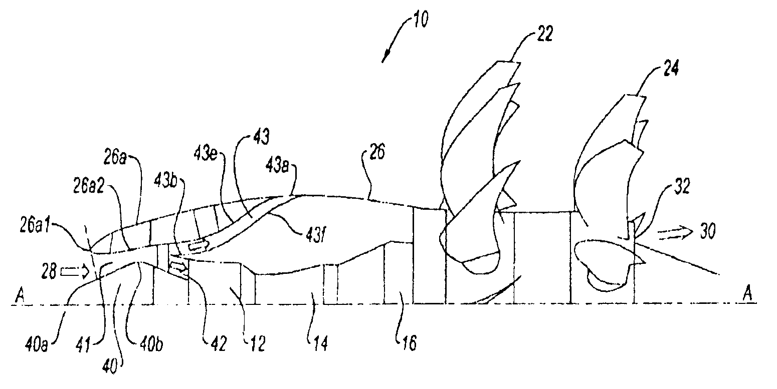
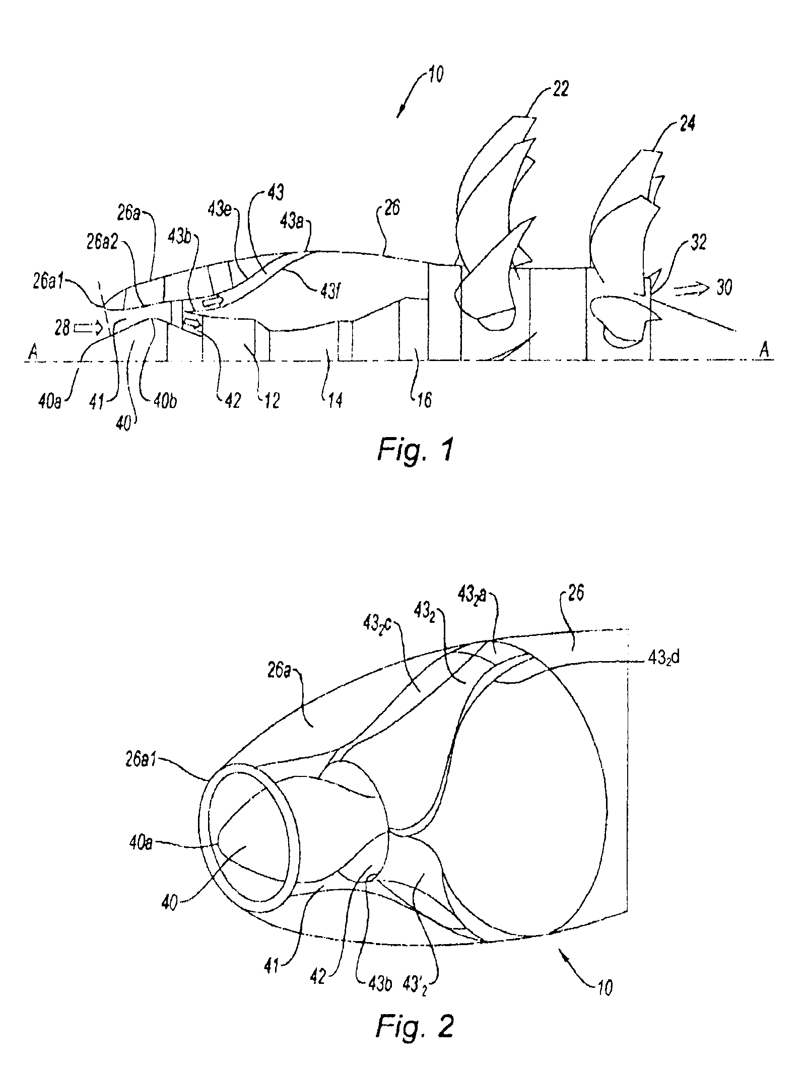
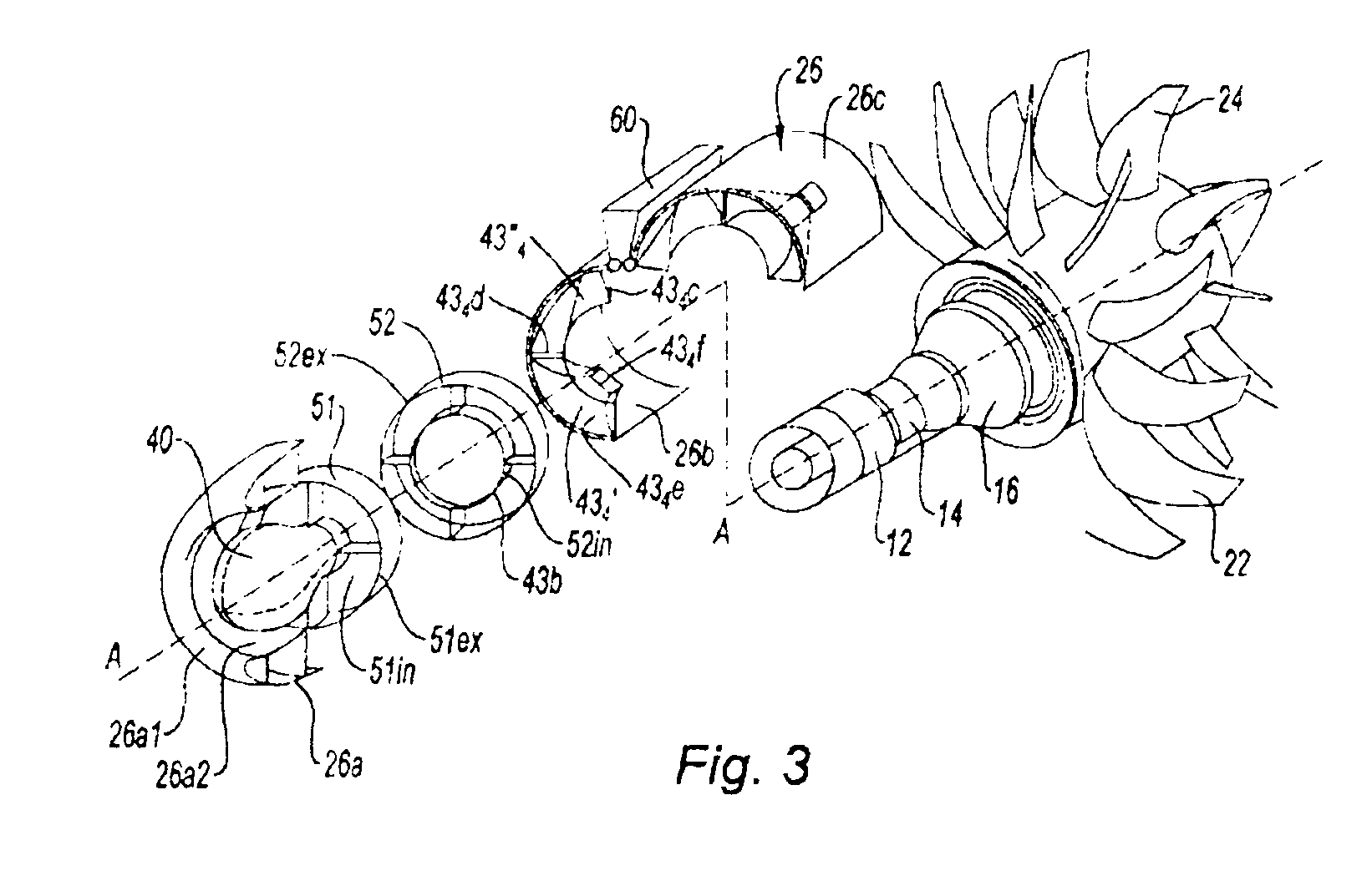
[0045]Reference is made first of all to FIG. 1 which depicts the main constituent parts of an unducted fan turbine engine 10. From upstream to downstream, in the direction in which the gases flow within the turbine engine, it comprises a compressor 12, an annular combustion chamber 14, a high-pressure turbine 16 only the casings of which are visible. Downstream of the high-pressure turbine 16 are two low-pressure turbines, not visible, which are contrarotatory, which means to say that they rotate in opposite directions about the longitudinal axis A of the engine.

[0046]Each of these downstream turbines rotates as one with an external set of fan blades 22, 24 extending radially on the outside of the nacelle 26 of the turbine engine, this nacelle 26 being substantially cylindrical and extending along the axis A from the air inlet around the compressor 12, the combustion chamber 14 and the turbines.

[0047]The flow of air 28 that enters the engine is compressed and then mixed with fuel an...


PUM


Abstract

An assembly including a gas turbine engine and a nacelle in which the engine is housed, the nacelle including an air intake fairing that forms an air inlet and includes: a member for deflecting foreign objects, which together with the fairing, forms an air intake duct; and, downstream from the deflecting member, a secondary deflecting channel, and a main channel for supplying air to the engine. The air intake duct is configured to deflect at least some of the foreign objects sucked in through the air inlet towards the secondary deflecting channel. The secondary deflecting channel is shaped such that the flow velocity of the air flowing therethrough increases from upstream to downstream, the secondary channel having an outlet with an opening leading into the outer wall of the nacelle.

Description

BACKGROUND OF THE INVENTION[0001]1. Field of the Invention[0002]The present invention relates to the field of aeronautical turbine engines and is aimed in particular at the air inlet of the turbine engine, the latter comprising the engine itself and the nacelle in which it is housed.[0003]2. Description of the Related Art[0004]A turbine engine generally comprises a gas generator formed of one or more sets of rotors rotating about one and the same axis. Each set, known as a spool, is made up of a compressor and of a turbine which are usually connected by a shaft or drum, and are arranged one upstream and the other downstream of a combustion chamber in relation to the flow of gases through the engine. Associated with this gas generator is a fan or a simple or multiple set of fan blades that it drives.[0005]When the rotor of the fan or set of fan blades is positioned in front of the engine, the air inlet of the generator is situated downstream of this rotor. Foreign bodies, such as bir...

Claims


Application Information

Patent Timeline
Patent Type & Authority Patents(United States)
IPC IPC(8): F02C7/052F02K3/072B64D33/02F02C7/05F02C7/20F02K3/062B64D27/00
CPCF02C7/05B64D33/02F02C7/052F02C7/20F02K3/062F02K3/072B64D2027/005B64D2033/022B64D2033/0293F05D2250/292F05D2250/70F05D2260/607Y02T50/66Y02T50/671Y02T50/675Y02T50/60
Inventor CHANEZ, PHILIPPE GERARDMABBOUX, GAETAN JEANMINOT, PHILIPPE GILLESVINCENT, THOMAS ALAIN CHRISTIANYVON, DIDIER JEAN-LOUIS
Owner SN DETUDE & DE CONSTR DE MOTEURS DAVIATION S N E C M A
Why Eureka
Try Eureka