
Magnetic football helmet to reduce concussion injuries

a magnetic football and helmet technology, applied in the field of protective headwear, can solve the problems of nerve damage, brain bruising, blood vessel damage, etc., and achieve the effects of reducing impact force, reducing impact force, and slowing collision speed

Inactive Publication Date: 2017-06-27
VIRGINIA COMMONWEALTH UNIV
View PDF135 Cites 9 Cited by
  • Summary
  • Abstract
  • Description
  • Claims
  • Application Information

AI Technical Summary

Benefits of technology

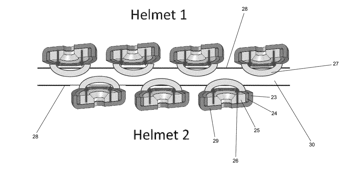
The patent describes a protective helmet that uses magnetic elements to slow down collisions and reduce impact force during helmet-to-helmet collisions. The magnetic elements create a repulsive force that helps to mitigate damage and potential concussions, which could help to reduce the number of concussions on the field. The helmet design uses existing pads and a combination of magnetic elements to create a multi-layered system that works together to protect the helmet wearer.

Problems solved by technology

Concussions, otherwise known as Traumatic Brain Injury or TBI, are a major cause of morbidity and mortality in the US, and thus represent a public health issue that costs society money and lives.
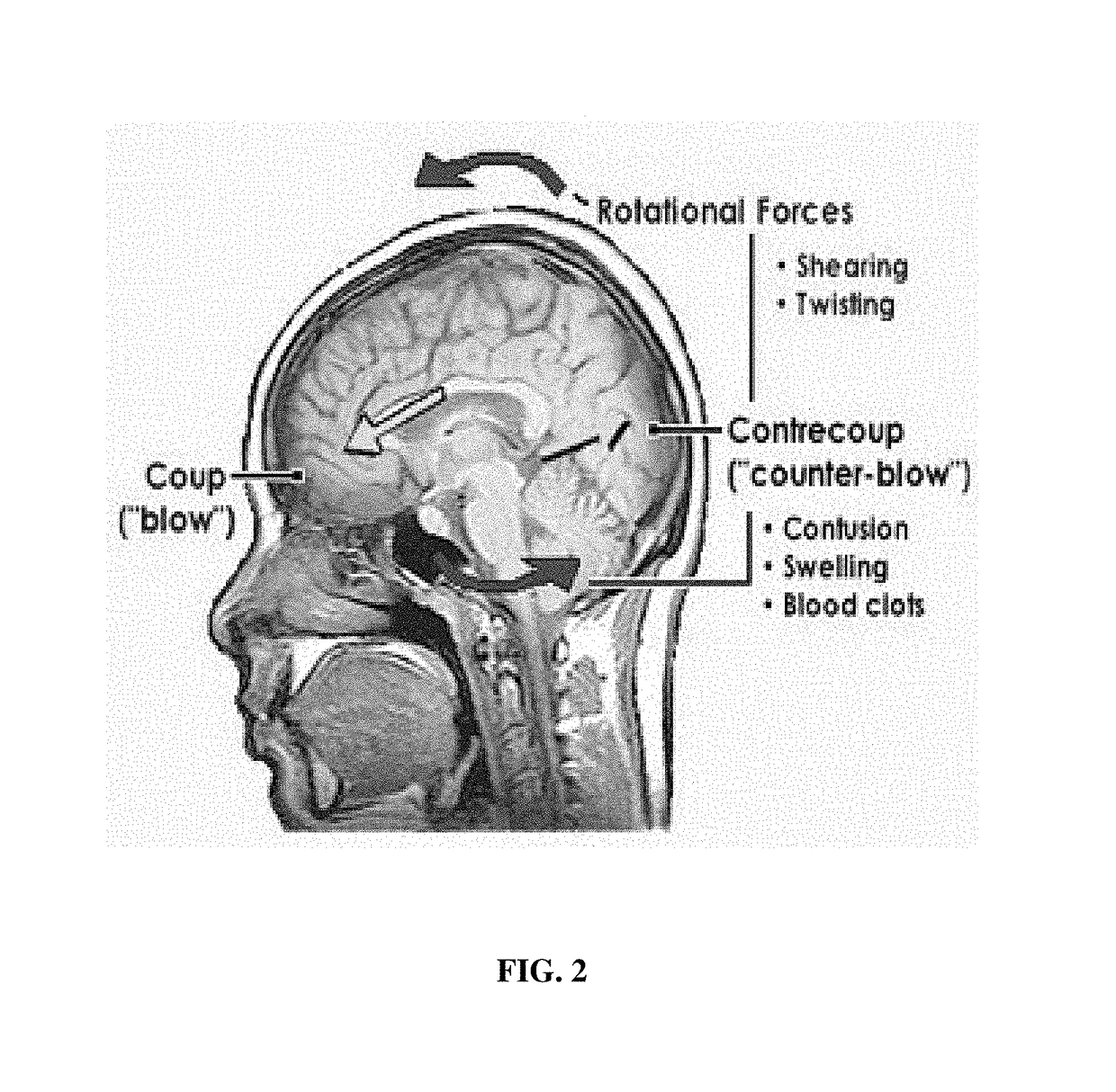
The impact may cause bruising of the brain, tearing of blood vessels, and nerve damage.
The initial blow is termed the “coup” and the damage to the other side of the brain is termed the “contrecoup” or counter-blow, and this counter-blow often results in confusion, swelling, and blood clots.
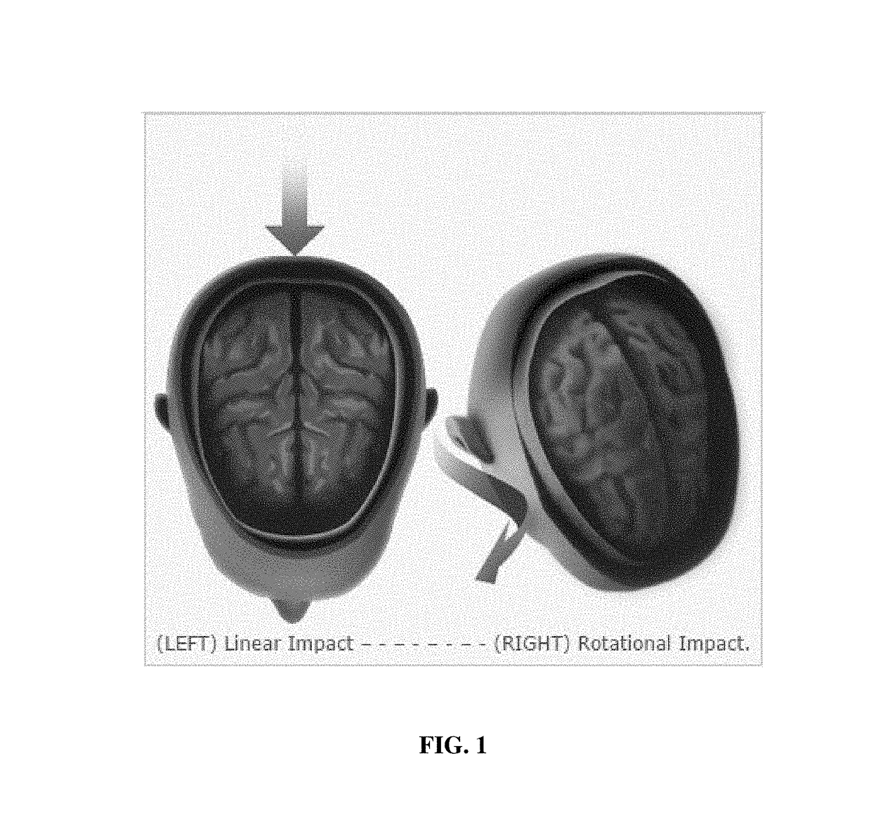
Additionally, rotational forces from angular blows may occur resulting in shearing and twisting of the brain within the skull (FIG. 2).
TBI in contact sports leagues like the NFL are a big and expensive problem.
Additionally, it is desirable that any design improvements not significantly add to the weight of the helmet as this would become uncomfortable and cumbersome for the players.
To date, however, magnets have not been properly incorporated in protective helmet technology to decelerate impact, reduce collision forces, and mitigate neck injuries stemming from laminar motion and the sticking together of helmets—both of which would be caused by magnet configurations described in the prior art.
In some instances, the existing helmets comprising magnets do not differentiate between coup and countercoup injuries, and described helmet designs would not mitigate both coup and countercoup injuries.
These cells would cushion a blow to the head, however, due to their small size, they may not decrease the actual impact velocity from a second identical helmet in a collision.
Such designs caused the helmets to stick together at some angles of impact and / or caused laminar motion between two opposing helmets.
In particular, existing helmets have magnets configured such that they act solely to repulse another identically configured magnetic helmet, neither providing any protection from the counter-coup that results from an impact which may occur nor protection from a near-uniform repulsive force around the head of the wearer of the helmet.
Such is not an optimal design for prevention of TBI, and actually would cause rotational energy to be applied to the neck of the wearer due to the shape of the magnetic field.
However, when the helmets are secured to human heads, the rapid change in vector can result in significant twisting / rotational force on the neck, causing muscular injury, injury to the cervical spine, and / or potentially injury to the spinal cord if the cervical spine is damaged significantly.

Method used


Image

  • Magnetic football helmet to reduce concussion injuries
  • Magnetic football helmet to reduce concussion injuries
  • Magnetic football helmet to reduce concussion injuries

Examples


example 1

ng the Strength of Repulsive Forces

[0113]The strength of the repulsive force of these magnets, as it relates to distance was measured. Specifically, the repulsive force of two N52 disc magnets with like poles facing each other was determined at equal intervals, from the distance where repulsive forces can be detected to the point of near magnet contact.

[0114]FIGS. 7A-7D demonstrate how much repulsive force the magnets are able to exert at a given distance. Neodymium magnets (12) were fixed to a machine press (11) (see FIG. 7A) and like poles (N,N) were moved in increments of 0.25 inches toward each other. Force was measured in pounds with the use of an analog scale (13) that was placed beneath the lower magnet. Repulsive force generated in the one magnet system by the two opposed magnets 0.75 inches apart is approximately 40 lbs.

[0115]In FIGS. 7B-7C, the experimental design is the same, however, in the presence of two 3.5 mm polycarbonate sheets (14) placed between the magnets (this...

example 2

tion of Whether Magnets can Reduce Impact Forces

[0118]To determine whether these magnets can reduce impact forces generated at a site of impact, magnet(s) were first secured in wood blocks adapted to slide smoothly on bars holding 10 lb metal weights (see FIGS. 8A and 8B). The repulsive force is generated by 2-inch diameter N52 magnets (single magnets with like poles facing each other with individual magnets (16) embedded in wooden chucks (15) on the rig shown in FIGS. 8A and 8B). Repulsive force was measured for both 10 lb (a) and 50 lb (b) stationary weights (each metal bar equals 10 lbs). The space between the two blocks of wood is the distance needed between two magnets (black arrow) to lift the corresponding weight. FIG. 8C shows a photograph of Fuji Prescale films placed between the magnets impacted by a 10 lb weight dropped from 6, 12, or 24 inches in the absence or presence of magnets. The experimental paradigm is comparable to current methodologies used to certify helmet sa...

example 3

ation of the Extent to which Magnetic Repulsion Reduces Forces at Impact

[0120]Using the experimental rig shown in FIGS. 8A-8B, deceleration and impact forces were measured for the drop assay described above using an accelerator (Bruel and Kjaer 4533-B), which was mounted to the top of the moving weight, and attached to a hand-held analyzer (Bruel and Kjaer 2250). The accelerometer data was measured in m / s2 and peak acceleration converted into g forces. As shown in the graph of FIG. 9, the solid line illustrates the peak acceleration with no magnet (negative control), the line with square data points illustrates peak acceleration with 2 pairs of opposing neodymium magnets, and the line with circle data points demonstrates the peak acceleration with 2 opposing pairs of magnets separated by 2 sheets of 3.5 mm polycarbonate. Table 1 shows numerical data from which the FIG. 9 graph is derived.

[0121]

TABLE1Quantification of Force Reduction at Impact (g = number of g forces)Magnet with No M...


PUM


Abstract

Helmets which harness magnetic forces to reduce the force of impact collisions to helmets during contact sports, thus reducing the likelihood that athletes sustain a physical injury such as a traumatic brain injury and / or a neck injury, are described. The helmets incorporate strong magnets into the shell such that a repulsive magnetic force is generated between opposing helmets, thus reducing impact forces. Each helmet includes a protective shell and at least one magnet which is arranged or configured to provide for a spatially modulated magnetic array.

Description

CROSS-REFERENCE TO RELATED APPLICATIONS[0001]This application claims priority to and the benefit of the filing dates of U.S. Provisional Application No. 61 / 936,509, filed Feb. 6, 2014, U.S. Provisional Application No. 62 / 075,019, filed Nov. 4, 2014, and U.S. Provisional Application No. 62 / 093,537, filed Dec. 18, 2014, the disclosures of which are hereby incorporated by reference herein in their entireties.FIELD OF THE INVENTION[0002]This disclosure relates generally to the field of protective headwear, and in particular, to the design of protective helmets, such as those used in athletic sports, which reduces the likelihood of traumatic brain injury (TBI) and neck injury from linear and rotational blows to the head sustained while participating in contact sports.BACKGROUND OF THE INVENTION[0003]Concussions, otherwise known as Traumatic Brain Injury or TBI, are a major cause of morbidity and mortality in the US, and thus represent a public health issue that costs society money and li...

Claims


Application Information

Patent Timeline
Patent Type & Authority Patents(United States)
IPC IPC(8): A42B3/04A42B3/06
CPCA42B3/0406A42B3/069
Inventor COLELLO, RAYMOND J.CAFFREY, REBECCA E.
Owner VIRGINIA COMMONWEALTH UNIV
Learn More