Method of manufacturing cylinder with interchangeable sleeve

a technology of rotating cylinders and sleeve sleeves, which is applied in the direction of manufacturing tools, portable power-driven tools, and ways, etc., can solve the problems of reducing the production efficiency of cylinders

Inactive Publication Date: 2008-04-15
FABIO PERINI SPA
View PDF15 Cites 2 Cited by
  • Summary
  • Abstract
  • Description
  • Claims
  • Application Information

AI Technical Summary

Benefits of technology

[0020]In this way, a secure and reliable fit is obtained. Moreover, this type of fit allows advantageously the interchangeable sleeve to be made of substantially rigid material and avoids the use of compressed air for expanding the sleeve so as to facilitate extraction and insertion from / onto the central inner core. The rigidity of the sleeve eliminates the problem of relative rolling or slipping of the sleeve and central inner core.
[0021]Moreover, since it is not required to use elastically yielding materials in order to form the interchangeable sleeve, the latter may be formed with a central component consisting of carbon fiber or carbon-fiber reinforced polymerized resin. This material allows the application of a metallic layer on the external surface of the interchangeable sleeve. In this way it is possible to manufacture sleeves with raised patterns which are made of metal and are therefore particularly hard and wear-resistant and advantageous for use in embossing cylinders.
[0027]According to a further aspect. It is an object of the invention to provide interchangeable embossing sleeves or sleeves for similar uses, by means of a simple and easily repeatable method.
[0035]Using a same core, which basically forms the core of the embossing cylinder or other cylinder intended for the processing of a web-like material, it is possible to construct several interchangeable sleeves, which can all be perfectly mated with the core with which they have been produced. In this way it is possible to obtain a system composed of a core and a plurality of interchangeable sleeves constructed on the core itself. By combining now one or other of said sleeves with the core, composite embossing cylinders with variable patterns are obtained, since each sleeve may have its own embossing pattern.
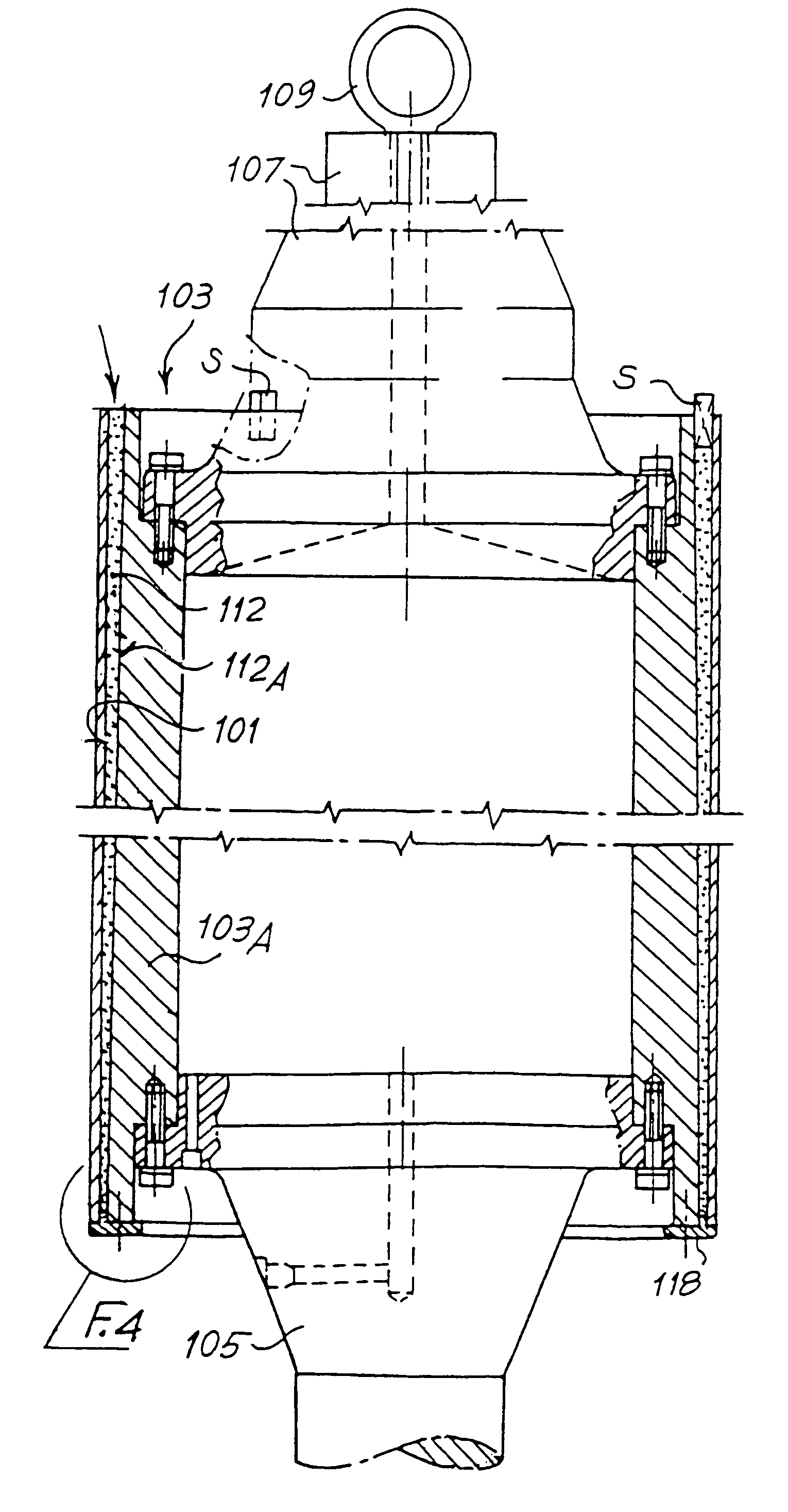
[0039]An annular centering and sealing flange may be placed between the cylindrical sleeve and the larger-diameter end of the core, in order to prevent the escaping of liquid resin and center the core and sleeve relative to each other. Segments centering said sleeve and the smaller-diameter end of said core may be adopted at the end positioned at the top, for casting of the resin, which may be performed between spaced segments.
[0040]Advantageously, according to a further development of the present invention, after hardening of the resin, the external surface of the sleeve is ground and then engraved so as to produce embossing reliefs or the like on its external surface. Grinding and engraving may be performed directly after hardening, without removing the sleeve from the core. Alternatively, it is possible to extract the sleeve with the layer of resin adhering to it from the core and then reinsert the sleeve onto the core, if necessary after cleaning the surface of the core, in order to eliminate residues of the separating agent or other material.

Problems solved by technology

One of the problems which arises in this particular technology consists in the need to change the embossing patterns with a certain frequency, when passing from one production batch to another one, so as to adapt to the varying characteristics of the material used, in order to satisfy different requirements and / or markets.
Similar problems arise during the printing of web-like material, in particular paper material.
The costs of the cylinder and the engraving operations are extremely high.
This means that, in order to have a certain number of interchangeable embossing patterns available, it is required to stock a corresponding number of high-cost cylinders and particularly time-consuming operations are also required of personnel in order to replace the cylinders with a consequent loss of production due to the machine downtime.
One of the drawbacks which arises in this type of solution, and in particular in the embossing sector, consists in the tendency of the sleeve to slip or roll on the central core of the cylinder.
This slipping effect results in problems of wear and, in particular in double units, in a phase-displacement in the relative position of the incisions on the two embossing rollers.
This solution however is not satisfactory in particular when the interchangeable sleeve is made of fiberglass.

Method used


Image

  • Method of manufacturing cylinder with interchangeable sleeve
  • Method of manufacturing cylinder with interchangeable sleeve
  • Method of manufacturing cylinder with interchangeable sleeve

Examples


Embodiment Construction

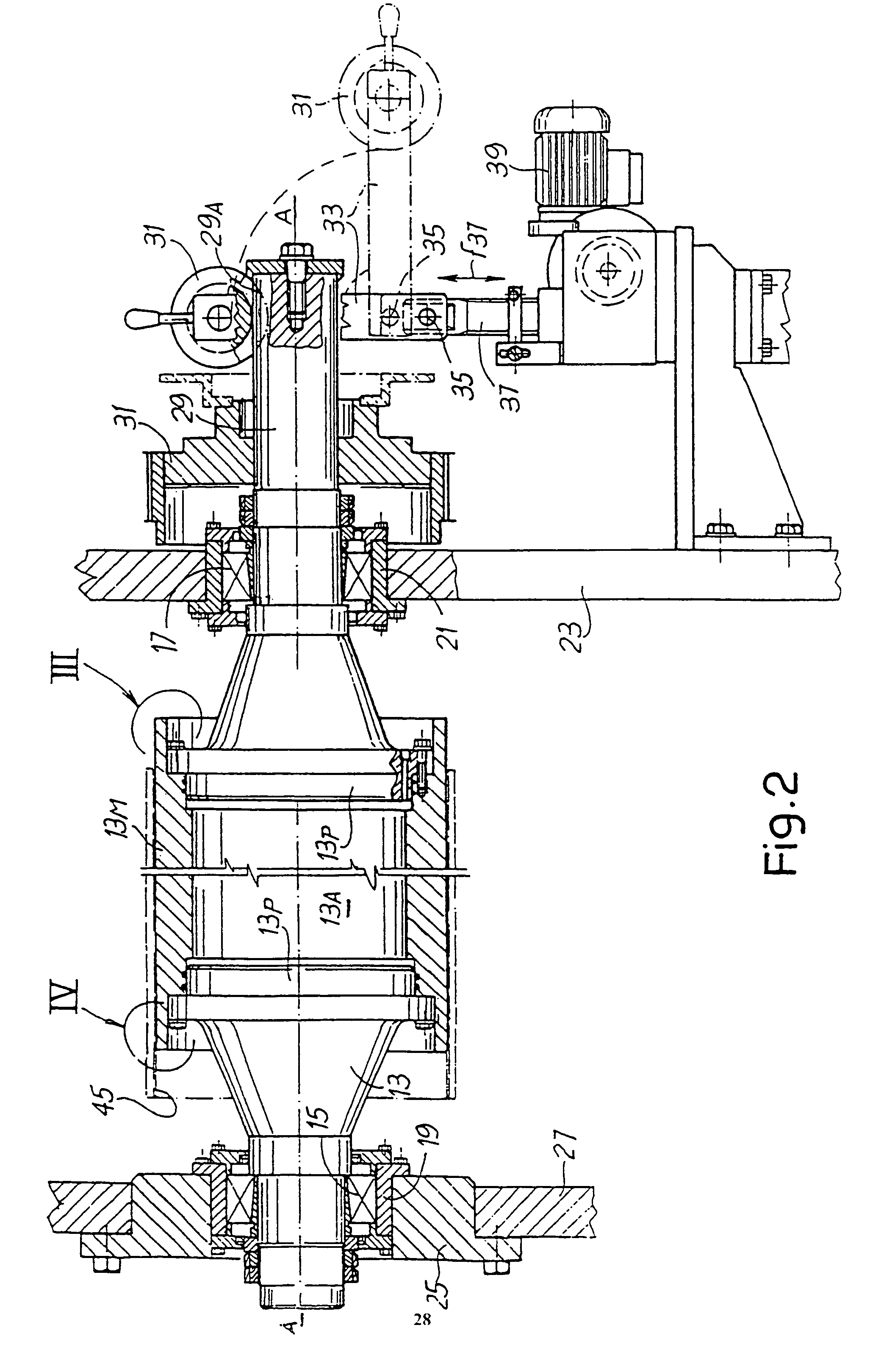
[0054]A first embodiment of the invention will now be described with reference to FIGS. 1 to 4.

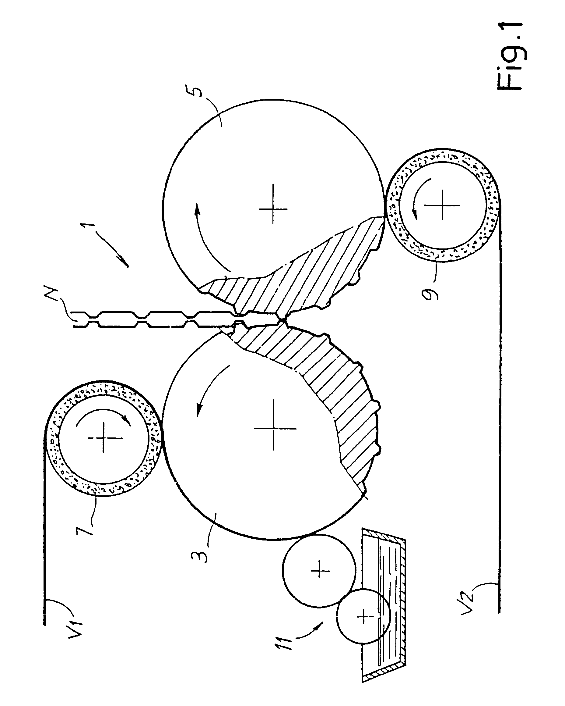
[0055]FIG. 1 shows in very schematic form an embossing unit, generally indicated by 1, in which the present invention may be used. It must however be understood that the principles underlying the invention may also be applied in the manufacture of embossing cylinders intended for embossing units of another type, for example “nested” units or also individual embossers. Moreover, the invention may also be used for the manufacture of cylinders for processing web-like materials, able to perform operations other than embossing, for example printing or other processing operations which require rapid replacement of an interchangeable sleeve fitted onto the cylinder, whenever problems of angular slipping between interchangeable cylinder and central core of the cylinder occur.

[0056]The embossing unit 1 is of the so-called tip-to-tip type and has a first embossing cylinder 3 and a second embossing c...


PUM

PropertyMeasurementUnit
diameteraaaaaaaaaa
volumeaaaaaaaaaa
softnessaaaaaaaaaa

Abstract

The rotating cylinder comprises: an elongated inner core (12) which is substantially rigid and an interchangeable sleeve (45) which is fitted onto the core; the sleeve is axially and angularly constrained to said core and is provided on its external surface with a raised pattern. The internal surface of the interchangeable sleeve and the external surface of the inner core are conical surfaces which are mutually complementary; axial and angular locking of the interchangeable sleeve and the inner core is achieved by the friction between the conical surfaces which are forced axially one onto the other.

Description

TECHNICAL FIELD[0001]The present invention relates to a rotating cylinder for processing a web-like material, and in particular but not exclusively to an embossing cylinder for embossing materials in sheet form, such as tissue paper or the like. More particularly, the invention relates to a rotating cylinder of the type comprising a substantially rigid, central, inner core on which an interchangeable sleeve is fitted.[0002]The invention also relates to a device comprising at least one rotating cylinder of the abovementioned type, for example an embossing unit or a printing unit.[0003]The invention also relates to an interchangeable sleeve for a rotating cylinder, in particular an embossing cylinder or a printing cylinder of the type mentioned above.[0004]According to a further aspect, the invention relates to a method for manufacturing embossing cylinders or similar cylinders, such as printing cylinders, for the processing of strip-like materials, such as paper, tissue-paper or the ...

Claims


Application Information

Patent Timeline
Patent Type & Authority Patents(United States)
IPC IPC(8): B29C63/18B29C39/10B31F1/07
CPCB31F1/07B31F2201/072B31F2201/0723B31F2201/0728B31F2201/073B31F2201/0753B31F2201/0766B31F2201/0776B31F2201/0787
Inventor BETTI, GIULIOLORENZI, FABRIZIODI NARDO, WALTER
Owner FABIO PERINI SPA
Why Eureka
Try Eureka