Printing apparatus

a printing apparatus and printing technology, applied in the field of printing apparatus, can solve the problems that the linear tone reproduction curve cannot be solved in the conventional printing apparatus, and the linear tone reproduction curve cannot be solved in the conventional printing apparatus, and achieve the effect of excellent linear tone reproduction curv

Active Publication Date: 2008-04-15
OKI ELECTRIC IND CO LTD
View PDF3 Cites 4 Cited by
  • Summary
  • Abstract
  • Description
  • Claims
  • Application Information

AI Technical Summary

Benefits of technology

[0022]The printing apparatus according to this invention can adjust a domain having the optical density decreasing as opposed to increase of the recording energy since converting the tone value into the driving pattern such that a ratio between the entire amount of recording energy of the image elements composing one pixel and an increment of the optical density is set to greater than or equal to 0 with respect to increase of the tone value.
[0025]In the printing apparatus according to this invention, the driving pattern converter may convert a driving pattern for a domain having the optical density decreasing as opposed to increase of the recording energy in the driving pattern data into a driving pattern providing small recording energy and the maximum optical density. Also, the driving pattern converter may eliminate the driving pattern for the domain having the optical density decreasing as opposed to increase of the recording energy.
[0027]The printing apparatus according to this invention can adjust a domain having the optical density decreasing as opposed to increase of the recording energy since converting the tone value into the driving pattern such that a ratio between the entire amount of recording energy of the image elements composing one pixel and an increment of the optical density is set to greater than or equal to 0 with respect to increase of the tone value, at the time of exposing the electrostatic latent image carrier.
[0029]The printing apparatus according to this invention can adjust a domain having the optical density decreasing as opposed to increase of the recording energy since converting the tone value into the driving pattern such that a ratio between the entire amount of recording energy of the image elements composing one pixel and an increment of the optical density is set to greater than or equal to 0 with respect to increase of the tone value, at the time of exposing the electrostatic latent image carrier using the exposing unit arrayed with the plurality of exposure elements in an array form.
[0030]According to this invention, the excellent linear tone reproduction curve can be realized upon determining a relative position of the exposed locations in consideration of interaction of a combination of the plurality of exposure amounts for forming one pixel.

Problems solved by technology

The conventional printing apparatus, however, has a problem with a linear tone reproduction curve even where adopting any driving methods as described above since the cumulative exposure amount is set to a parameter used for modulation of image data.
As described above, the problem with the linear tone reproduction curve cannot be solved in using the conventional printing apparatus.

Method used


Image

  • Printing apparatus
  • Printing apparatus
  • Printing apparatus

Examples


first embodiment

[0086]The printing apparatus is described first.

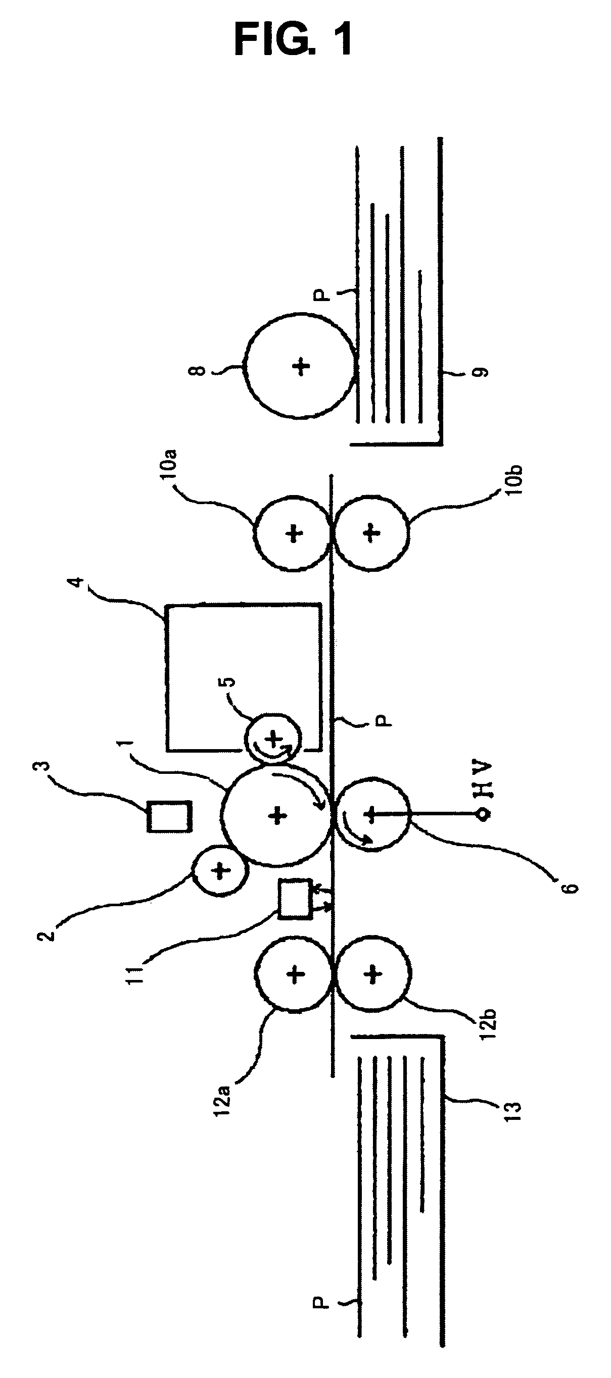
[0087]As shown in FIG. 1, the printing apparatus has a photosensitive drum 1 for forming an electrostatic latent image, a charging roller 2 to which high negative voltage is applied to charge a surface of the photosensitive drum 1 to predetermined negative voltage, and an LED head 3 in which the LED elements are arranged in an array form. The printing apparatus forms the electrostatic latent image on the charged photosensitive drum 1 upon selectively rendering the LED elements composing the LED head 3 emit the light. In the meanwhile, the LED head 3 is configured as a tone head capable of expressing density-tone according to input of data of multiple bits and can change an energy amount which is applied to every pixel.

[0088]The printing apparatus has a developing unit 4 for developing with toner the electrostatic latent image formed on the photosensitive drum 1. The developing drum 4 charges and supplies the toner to the developing ro...

second embodiment

[0134]The printing apparatus is described next.

[0135]With the printing apparatus according to the second embodiment, a tone value per pixel is modulated based on a luminous intensity, not on the emission time of each LED element likewise the first embodiment. In the second embodiment, the elements substantially the same as those in the first embodiment are assigned with the same reference numbers so that those duplicated description are omitted.

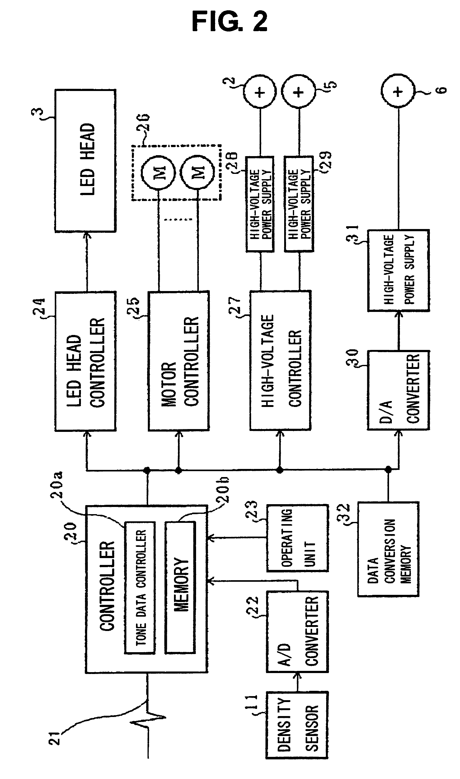
[0136]The printing apparatus according to the second embodiment realizes such a function as shown in FIG. 24 in using the controller 20 and the LED head controller 24.

[0137]To be more specific, the printing apparatus has a strobe intensity control circuit 61 in addition to the image data line buffer 51, the driving pattern converter 52, and the line synchronization signal generating circuit 54.

[0138]Every time the m-line synchronization signal generated by the line synchronization signal generating circuit 54 arrives, the strobe intensity co...

third embodiment

[0143]The printing apparatus is described next.

[0144]The printing apparatus according to the third embodiment has measures against the printing operation in binary mode, in addition to having the same tone expression capacity as that in the first embodiment. Therefore, in the third embodiment, the elements substantially the same as those in the first embodiment are assigned with the same reference numbers so that those duplicated description are omitted.

[0145]The printing apparatus according to the third embodiment realizes such the function as previously shown in FIG. 3 in using the controller 20 and the LED head controller 24. Herein, the image data transmitted from the host apparatus in a case of printing in the binary mode are composed of 5 bits per pixel but only the least significant bit PIX[0] or the most significant bit PIX[31] is transmitted and the other values are not transmitted.

[0146]In the printing apparatus as described above, on the condition that the image data com...


PUM


Abstract

A printing apparatus for printing an image onto a recording medium based on input image data, comprises an electrostatic latent image carrier for forming an electrostatic latent image, and an exposure controller for forming the electrostatic latent image corresponding to one pixel upon exposure of the electrostatic latent image carrier with a combination of a plurality of different exposure amounts, wherein the exposure controller performs the exposure with the combination of the plurality of exposure amounts in a manner to satisfy a condition for an index value LNR expressed by a following general equation (1) using an optical density od (n) standardized on the condition of the maximum optical density equal to 1.0, identification information comb assigned to identify each combination of the plurality of exposure amounts, and the number of varieties m of a cumulative exposure amount used for modulation of the image data.LNR≤2 / m⁢⁢LNR⁡(comb)=∑n=0m-3⁢[{(od⁡(n+2)-od⁡(n+1))-(od⁢(n+1)-od⁡(n))}2] / (m-2).(1)

Description

BACKGROUND OF THE INVENTION[0001]1. Field of the Invention[0002]This invention relates to a printing apparatus for printing an image on a recording medium based on input image data.[0003]2. Description of Related Art[0004]Conventionally known as a printing apparatus is such as employing an electrophotographic process in which images are formed upon fixation of toner on predetermined recording media, and especially such a printing apparatus as achieving a tone-expression has been proposed (see, e.g., Japanese Patent Laid-Open No. H08-230234). In the printing apparatus as achieving the tone-expression, time required to expose one pixel is divided into predetermined time periods to set different exposure amount for each time period. The printing apparatus as described above adopts a driving method in which an exposing section is selectively enabled or disabled for each time period based on image data to correspond tone of the image information upon control of a cumulative exposure amou...

Claims


Application Information

Patent Timeline
Patent Type & Authority Patents(United States)
IPC IPC(8): B41J2/47B41J2/385B41J2/435
CPCG03G15/0415G03G15/043G03G2215/04
Inventor YAJI, MASAONAKASENDO, TAKASHI
Owner OKI ELECTRIC IND CO LTD
Why Eureka
Try Eureka