Compact optical engine for very small personal projectors using LED illumination

a technology of led illumination and compact optical engine, which is applied in the direction of lighting and heating apparatus, instruments, television systems, etc., can solve the problems that the engine technology developed for the conventional arc lamp and color wheel illumination system of single-panel digital micromirror devices (dmds) is not optimized for form, size, function, performance, etc., to minimize the power consumption and optical complexity, and reduce the cost of operation

Active Publication Date: 2008-04-22
TEXAS INSTR INC
View PDF9 Cites 24 Cited by
  • Summary
  • Abstract
  • Description
  • Claims
  • Application Information

AI Technical Summary

Benefits of technology

[0004]Some embodiments of the present invention provide numerous technical advantages. Other embodiments may realize some, none, or all of these advantages. For example, various illustrative embodiments may provide a device for a light projection system that creates a very compact optical system for a 0.55 inch (0.55″) panel diagonal digital micromirror device (DMD), having a form factor that remains no more than about 35 mm in thickness, with a total optical engine volume of no more than about 80 cc. A total projector using such a device for a light projection system, including electronics, a digital micromirror device (DMD) and a thermal solution to dissipate heat produced may have a total volume of no more than about 200 cc, weigh no more than about 1 lb, and be able to fit in a pocket and / or a purse. The brightness of such a projector using such a device for a light projection system may be no less than about 15 to about 20 lumens, and battery operation of such a projector may be in a range of about 2 to about 4 hours, so power consumption of the sources and the thermal solution may be minimal.
[0005]Similarly, various illustrative embodiments may provide a device for a light projection system that may use a single light emitting diode (LED) array, comprising at least one green die, at least one blue die, and at least one red die, disposed on a single high-power thermal package in such a way as to minimize substantially the power consumption and the optical complexity, and, thus, the overall size, weight, and volume of the light projection system. A single light collection, integration, and etendue-matching optic element comprising a tapered light pipe may be enabled by the single light emitting diode (LED) array, and may be compact, simple, and inexpensive. Coupling the at least one green die, the at least one blue die, and the at least one red die in air instead of using a conventional index-matching sealant may improve the optical efficiency and may enable use of the simple single light collection, integration, and etendue-matching optic element comprising the tapered light pipe.
[0006]A telecentric relay using at least one of spherical and aspherical refractive and reflective components may substantially minimize the overall volume and may also provide a pupil for controlling stray light. The telecentric relay may be manufacturable using relatively inexpensive technologies and / or materials due to the relatively low light levels.
[0007]In addition, using a coupling prism assembly comprising the right angle projection total internal reflection (TIR) prism and an illumination wedge prism may allow compact folding of the optical path within a single plane layout, in spite of the digital micromirror device (DMD) hinge axis being at about 45 degrees to the package. Moreover, using the coupling prism assembly may simplify assembly and substantially lower the cost and / or size / volume of a telecentric system by using standardized tooling, such as a 90 degree (right angle) projection total internal reflection (TIR) prism, and allowing reduction of projection lens offset to substantially the minimum field size required for market requirements and / or specifications. Furthermore, a plethora of standard liquid crystal display (LCD) lens designs may also be made applicable thereby.

Problems solved by technology

However, the optical engine technologies that were developed for conventional arc lamp and color wheel illumination systems for single-panel digital micromirror devices (DMDs) are not optimized for form, size, function, or performance when using light emitting diode (LED) sources.

Method used


Image

  • Compact optical engine for very small personal projectors using LED illumination
  • Compact optical engine for very small personal projectors using LED illumination
  • Compact optical engine for very small personal projectors using LED illumination

Examples


Embodiment Construction

[0019]Illustrative embodiments of the present invention are described in detail below. In the interest of clarity, not all features of an actual implementation are described in this specification. It will of course be appreciated that in the development of any such actual embodiment, numerous implementation-specific decisions must be made to achieve the developers' specific goals, such as compliance with system-related and business-related constraints, which will vary from one implementation to another. Moreover, it will be appreciated that such a development effort might be complex and time-consuming, but would nevertheless be a routine undertaking for those of ordinary skill in the art having the benefit of the present disclosure.

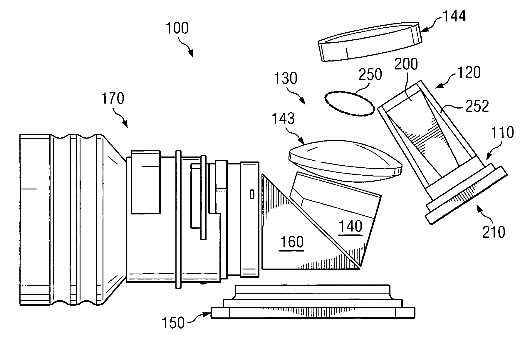
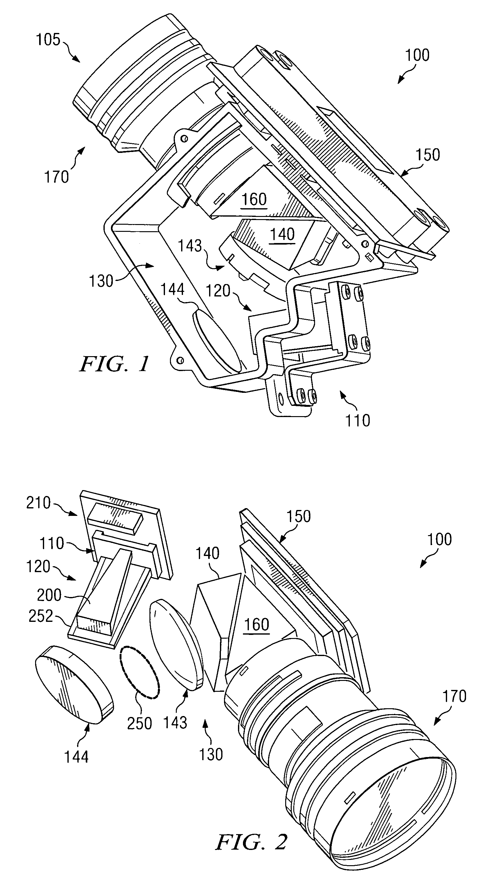
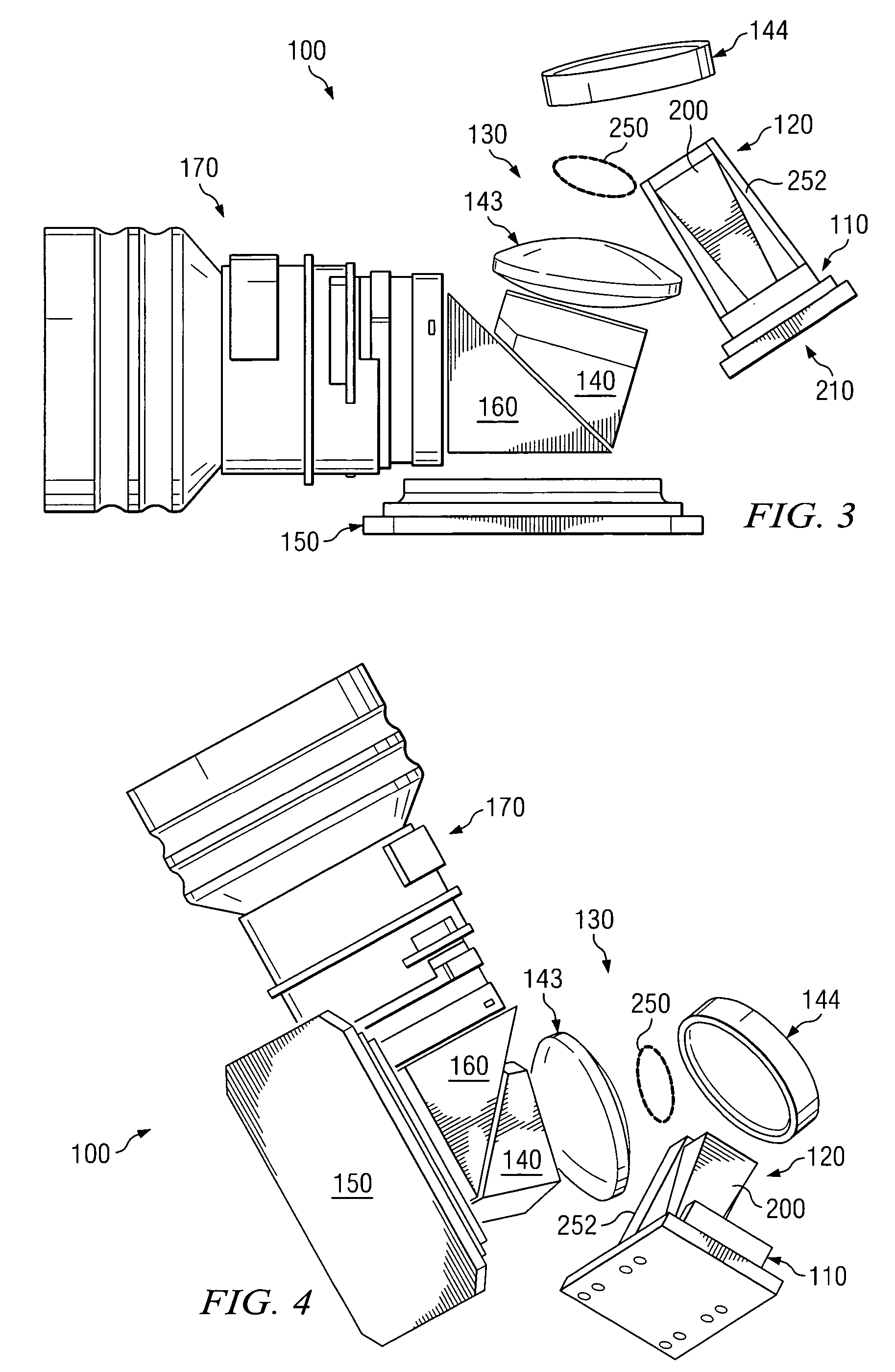
[0020]In various illustrative embodiments, as shown, for example, in FIGS. 1-8, a device 100 may be provided for a light projection system 105. As shown in FIGS. 1 and 8, the device 100 for the light projection system 105 may comprise a single light emitt...


PUM

PropertyMeasurementUnit
half angleaaaaaaaaaa
thicknessaaaaaaaaaa
thicknessaaaaaaaaaa

Abstract

According to various illustrative embodiments of the present invention, a device for a light projection system includes a single light emitting diode array comprising at least one green die, at least one blue die, and at least one red die, a single light collection, integration, and etendue-matching optic element comprising a tapered light pipe capable of collecting substantially all light emitted by the single light emitting diode array and spatially integrating the substantially all the light emitted by the single light emitting diode array, and a telecentric relay using at least one of spherical and aspherical refractive and reflective components. The device also includes an illumination wedge prism, a digital micromirror device capable of modulating the substantially all the light emitted by the single light emitting diode array, and a projection total internal reflection prism, the projection total internal reflection prism disposed between the illumination wedge prism and the digital micromirror device. The device also includes a projection lens, wherein the telecentric relay provides the substantially all the light emitted by the single light emitting diode array through the illumination wedge prism and through the projection total internal reflection prism to the digital micromirror device that reflects the substantially all the light emitted by the single light emitting diode array back through the projection total internal reflection prism that totally internally reflects the substantially all the light emitted by the single light emitting diode array through the projection lens.

Description

TECHNICAL FIELD OF THE INVENTION[0001]This invention relates to compact optical engine for very small personal projectors using light emitting diode (LED) illumination.BACKGROUND OF THE INVENTION[0002]Conventional attempts to use light emitting diode (LED) technology for small, “pocket-sized” or personal projection devices have relied on optical engine technologies that were developed for conventional arc lamp and color wheel illumination systems for single-panel digital micromirror devices (DMDs). However, the optical engine technologies that were developed for conventional arc lamp and color wheel illumination systems for single-panel digital micromirror devices (DMDs) are not optimized for form, size, function, or performance when using light emitting diode (LED) sources. For example, one major way that light emitting diode (LED) sources differ from arc lamps is that, though the emission area of a light emitting diode (LED) source is small, the light emitting diode (LED) sources ...

Claims


Application Information

Patent Timeline
Patent Type & Authority Patents(United States)
IPC IPC(8): G02F1/13357G03B21/28
CPCG03B21/28
Inventor DAVIS, MICHAEL T.DEWALD, D. SCOTT
Owner TEXAS INSTR INC
Why Eureka
Try Eureka