Rowing machine

Inactive Publication Date: 2008-04-22
CHUNG TING TSENG
View PDF12 Cites 14 Cited by
  • Summary
  • Abstract
  • Description
  • Claims
  • Application Information

AI Technical Summary

Benefits of technology

[0005]The present invention has been accomplished under the circumstances in view. It is one object of the present invention to provide a rowing machine, which permits the play

Problems solved by technology

However, such back and forth rowing exercises do not resemble actual rowing actions.
Further, the monotonous back and forth rowing exercises of conventional rowing machi

Method used


Image

  • Rowing machine
  • Rowing machine
  • Rowing machine

Examples


Embodiment Construction

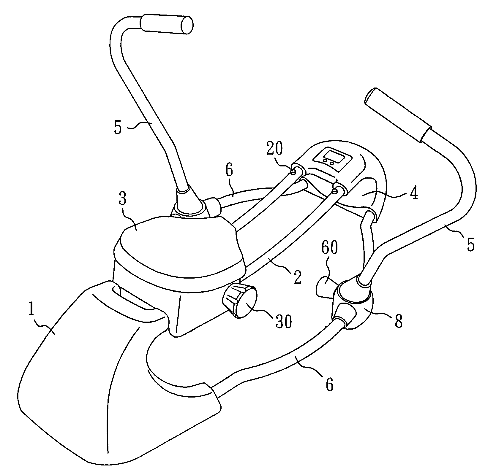
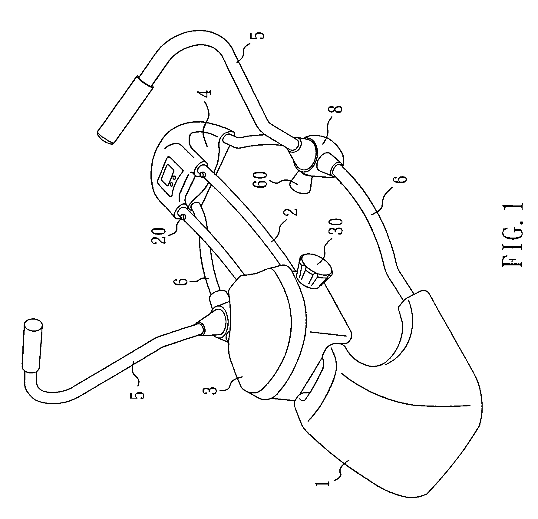
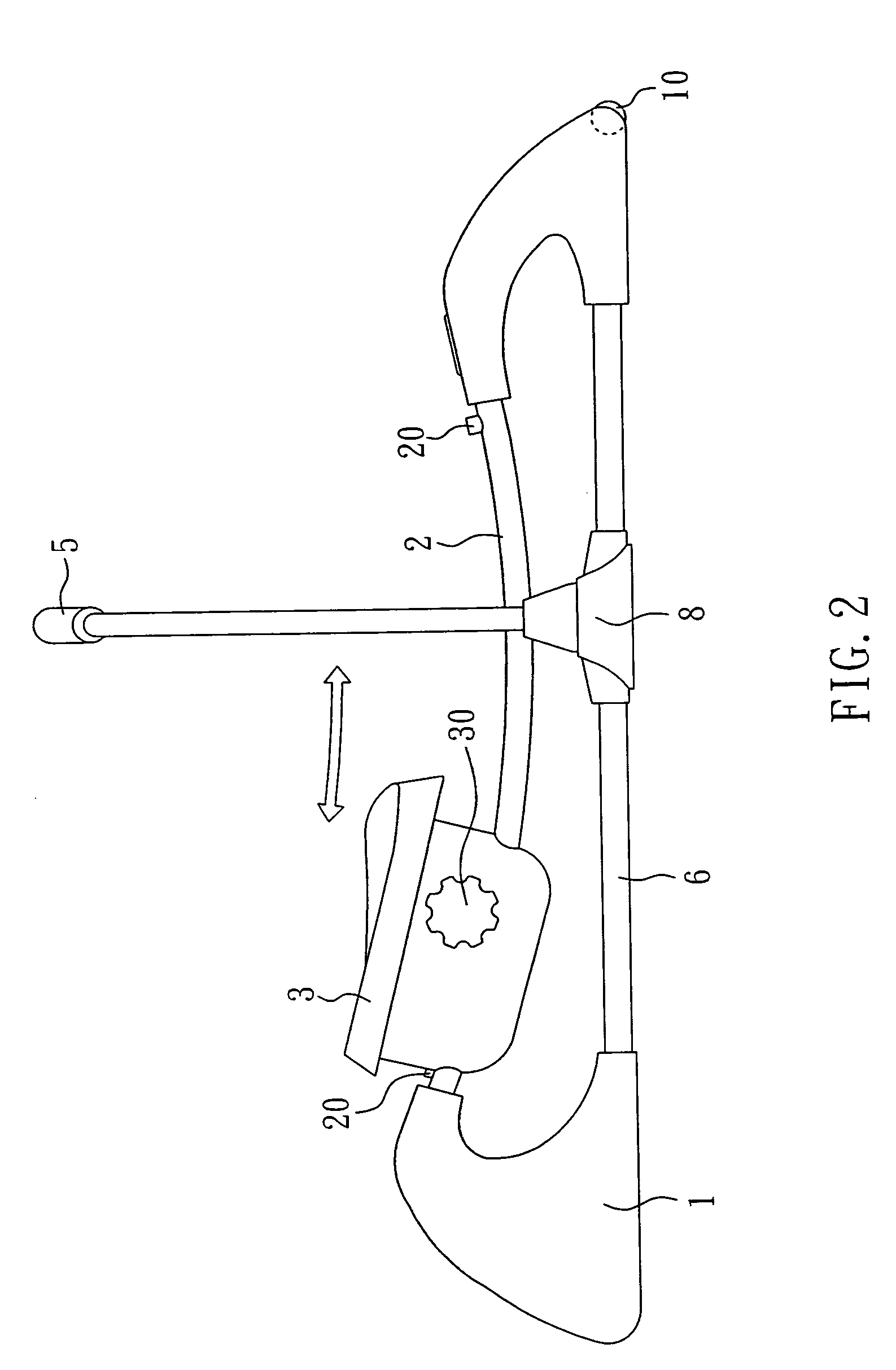
[0011]Referring to FIGS. 1˜4, a rowing machine in accordance with the present invention is shown comprising a machine base 1, a sliding track 2, a sliding seat 3, and two arm oars 5.

[0012]The machine base 1 is molded from plastics and shaped like a boat, having two footrests 4 at the front side for the resting of the user's feet and two side bars 6 symmetrically disposed at two opposite lateral sides. The two arm oars 5 are respectively connected to the side bars 6 with a respective universal joint 8. Each universal joint 8 has a friction pad 61 mounted on the inside and disposed in friction contact with the associating arm oar 5, and an adjustment knob (for example, an adjustment screw) 60 for adjusting the friction force between the friction pad 61 and the associating arm oar 5. The sliding track 2 can be a single-rail, dual-rail, or multi-rail design. It is fixedly mounted on the machine base 1 at the top side, having bumper rubbers 20 at the two distal ends. The sliding seat 3 i...


PUM


Abstract

A rowing machine, which includes a machine base, which has two footrests arranged at the front side, a sliding track disposed at the top side, and two sidebars at two sides, two arm oars respectively pivoted to the side bars of the machine base through a respective universal joint, two adjustment screws mounted in the universal units for adjusting friction between a respective friction pad in each universal joint and the associating arm oars, and a sliding seat slidably mounted the sliding track for sitting by the player and lockable to the sliding track by an adjustment knob.

Description

BACKGROUND OF THE INVENTION[0001]1. Field of the Invention[0002]The present invention relates to an exercising machine and more particularly, to a rowing machine, which permits the player to simulate actual rowing actions.[0003]2. Description of the Related Art[0004]Following improvement in living standards, people do more care about their health and in consequence, exercising apparatuses have become quite popular. Conventional rowing machines mainly permit back and forth movements to achieve physical exercises. However, such back and forth rowing exercises do not resemble actual rowing actions. Further, the monotonous back and forth rowing exercises of conventional rowing machines will make the user feel bored after a long period of use. U.S. Pat. No. 6,679,814 discloses an improved design of rower exerciser that permits the player to simulate actual rowing actions. However, this design of rower exerciser has a complicated structure, resulting in a high manufacturing cost.SUMMARY O...

Claims


Application Information

Patent Timeline
IPC IPC(8): A63B69/06A63B21/015
CPCA63B21/015A63B21/1492A63B22/0076A63B21/00069A63B22/0089A63B2022/0041A63B2022/0084A63B21/4047
Inventor CHUNG-TING, TSENG
Owner CHUNG TING TSENG
Why Eureka
Try Eureka