Aquatic object detection and disruption system
- Summary
- Abstract
- Description
- Claims
- Application Information
AI Technical Summary
Problems solved by technology
Method used
Image


Examples
Embodiment Construction
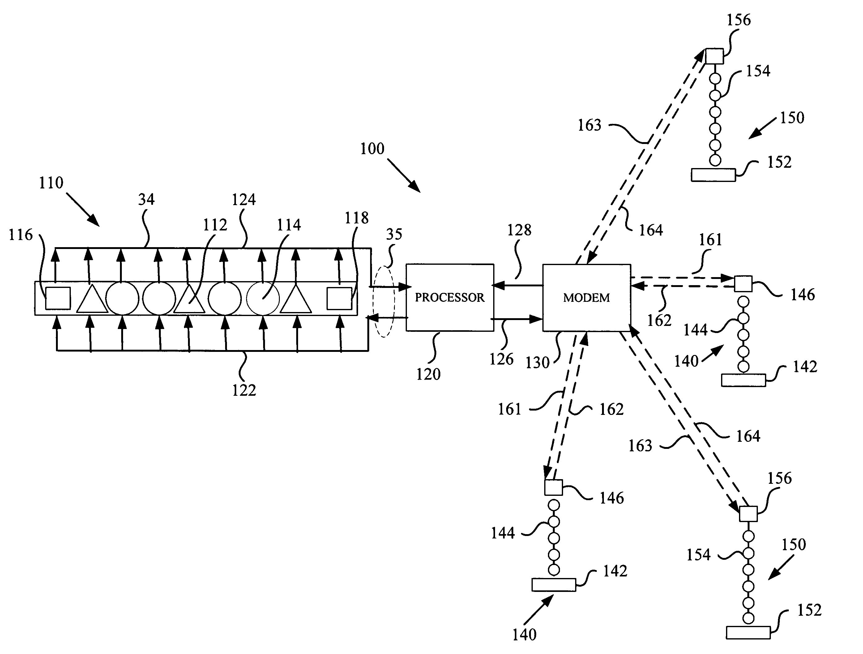
[0010]Referring to FIG. 1, there is shown a block diagram of an embodiment of the aquatic object detection and disruption system 10. System 10 includes a receive line array 20, a processor 30, a telesonar modem 40, a detection line array 50 and a disruption line array 60. Receive line array 20 may detect an object and transmit a receive line array signal representing such detection to processor 30. Processor 30 may process the receive line array signal and generate a detonation signal that is transmitted to telesonar modem 40. Telesonar modem 40 may transmit the detonation signal to detection line array 50 to detonate detection line array 50. In response to a signal received from a user of system 10, telesonar modem 40 may also transmit a detonation signal to disruption line array 60 to detonate disruption line array 60. Telesonar modem 40 can route the user-initiated detonation signal through processor 30 or can transmit the user-initiated detonation signal directly to disruption l...
PUM
 Abstract
Description
Claims
Application Information