Underwater measurement system

a measurement system and underwater technology, applied in the direction of instruments, fault location by conductor type, reradiation, etc., can solve the problems of reducing the quality of measurement, reducing the detection rate of water flow, and reducing spurious signals. , the effect of improving the quality of measuremen

Active Publication Date: 2010-11-04
NAXYS
View PDF11 Cites 40 Cited by
  • Summary
  • Abstract
  • Description
  • Claims
  • Application Information

AI Technical Summary

Benefits of technology

[0012]The invention is of advantage in that the voltage sensors are capable of detecting electric fields generated by electrical faults in the underwater region, and the one or more hydrophones are able to detect corresponding acoustic signals corresponding to such faults, thereby enabling the faults to be more reliably and accurately identified.
[0054]Optionally, for reducing external interference and thereby obtaining an enhanced quality of sensing using the underwater measurement system, the data processing arrangement is distributed between the probe and the computing hardware. Digitizing of signals and executing preliminary processing of the signals near the sensor assembly is capable of enhancing system robustness to interference and a risk of loss of information content in the one or more signals.

Problems solved by technology

However, such methods of monitoring and inspection do not enable certain types of defects in structures to be detected, especially those of an electrical nature.
Raising an underwater cable for repair is often an extremely expensive operation and there is a great need to be able to detect locations whereat submerged cables and electrical equipment are potentially defective or have developed faults.
Optical inspection often provides an inadequate approach for identifying and localizing defects and faults.
Hostile aquatic environments can be subject to considerable water flows and other disturbances which render techniques hitherto employed unsuitable.
There thus arises a challenging technical problem of detecting electrical faults in hostile aquatic environments.
Performing tests by “megging” is not feasible in a situation for detecting an earth fault on an electrically-floating secondary winding of an underwater transformer.
There is no known contemporary method that is able to detect an earth fault associated with such a secondary winding of an underwater transformer without special instrumentation being built into the transformer for detecting occurrence of any such faults.
This special instrumentation is susceptible to increasing installation complexity and cost and represents a sub-optimal solution.
Transmission of a test signal into a transformer circuit is not satisfactory when the secondary side of the transformer is positioned in the sea bed and in operation.

Method used


Image

  • Underwater measurement system
  • Underwater measurement system
  • Underwater measurement system

Examples


Embodiment Construction

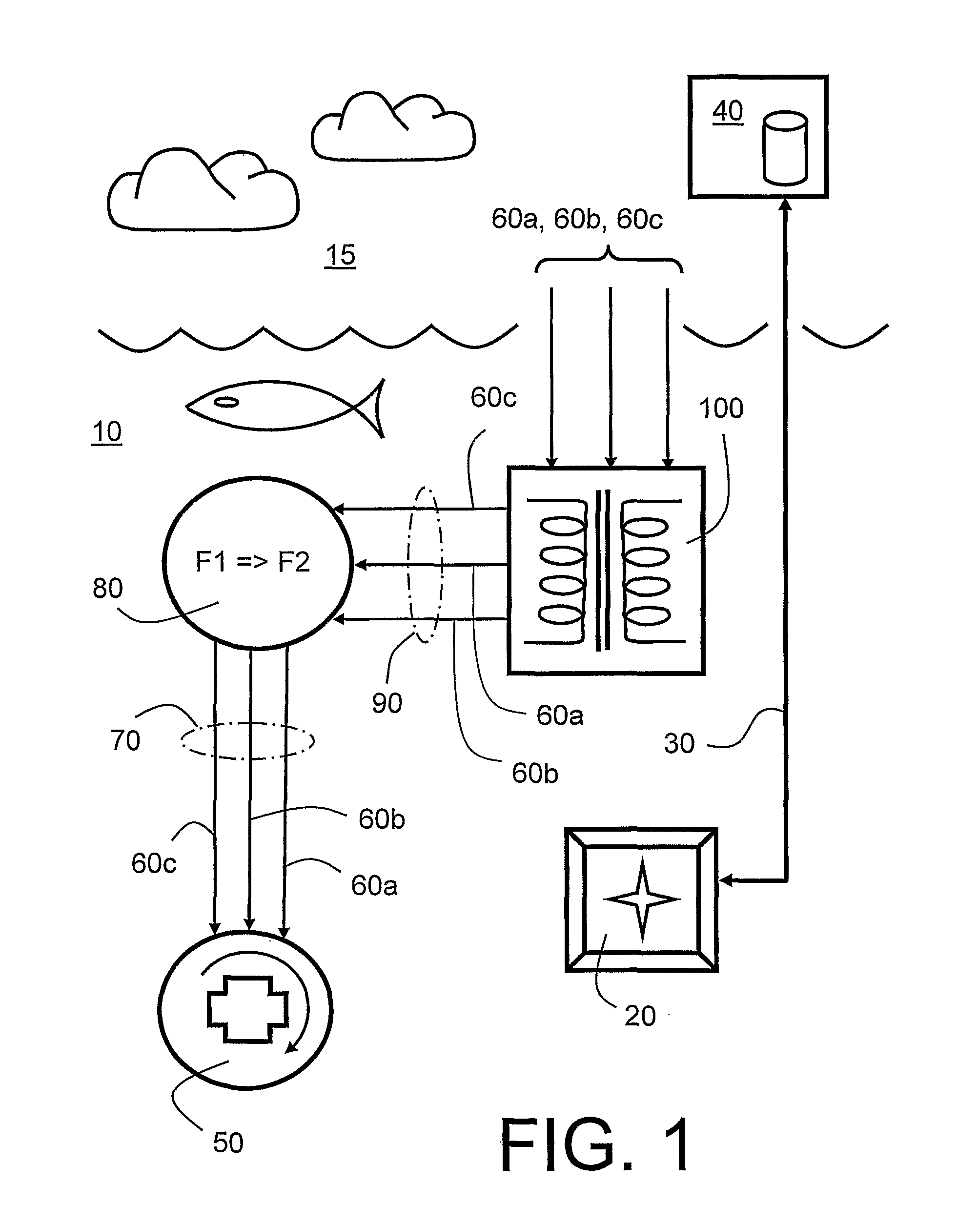
[0070]In connection with operations implemented in a marine environment where electrical power supply is necessary, for example for operating electrical pumps and similar, a breakage or other fault in the electrical supply can result in a critical situation or damage in such operations. It is advantageous to have available apparatus for detecting and warning of potential faults at an early point in time for avoiding consequences of eventual faults and associated damage. In oil and gas production where high-potential power distribution is essential, in view of a magnitude of electrical power flows occurring, safety is of paramount importance. In situations in which equipment is installed on the sea bed, for example at depths of many kilometres, it is impossible to employ conventional surveillance technology to identify potential faults. Consequences of electrical current leakage are more severe than land-based systems, because electrical leakage in conducting underwater environments ...


PUM


Abstract

There is provided an underwater measurement system (20, 30, 40) for monitoring an underwater region (10). The system (20, 30, 40) includes a sensor assembly operable to sense at least one physical variable in the region (10) for generating at least one corresponding sensor signal, and a data processing arrangement (170, 510, 520) for processing the at least one sensor signal to generate processed data for presentation and / or logging. The sensor assembly (20) includes one or more voltage sensors (190) configured to sense electric fields present in the underwater region (10) and provide information in the at least one signal indicative of the electric fields. Moreover, the sensor assembly (20) includes one or more hydrophones (200) operable to receive sonic energy generated in the underwater region (10) and to include corresponding information in the at least one sensor signal for communicating to the data processing arrangement (170, 510, 520).

Description

FIELD OF THE INVENTION[0001]The present invention relates to underwater measurement systems. Moreover, the invention concerns methods of monitoring underwater regions using aforesaid underwater measurement systems. Furthermore, the present invention relates to sensor configurations for implementing such methods. Additionally, the invention concerns software products conveyable on data carriers and executable on computing hardware for implementing such methods.BACKGROUND OF THE INVENTION[0002]Underwater vessels such as submarines are well known. More recently, mini-submarines have been used to monitor fish stocks for farm cultured salmon and for inspecting submerged structures in deep-sea oil exploration. Monitoring and inspection is often performed using optical cameras for capturing images of underwater regions, as well as employing active sonar equipment for emitting sonic energy and receiving corresponding sonic reflections from submerged structures.[0003]However, such methods of...

Claims


Application Information

Patent Timeline
Patent Type & Authority Applications(United States)
IPC IPC(8): G01V3/08G01R31/50
CPCG01V3/088G01R31/50G01R31/00G01R31/083G01V3/00G01R31/08G01R31/12G01R31/58
Inventor SAETHER, FRANK TORE
Owner NAXYS
Why Eureka
Try Eureka