Mutual capacitive touch panel

a capacitive touch panel and capacitive technology, applied in the field of capacitive touch panel, can solve the problems of affecting the sensing quality of the touch panel, and achieve the effects of preventing the reduction of the background capacitance of each sensing unit, improving the touch sensing quality, and improving the accuracy of touch

Active Publication Date: 2021-06-22
ILI TECHNOLOGY CORPORATION
View PDF10 Cites 0 Cited by
  • Summary
  • Abstract
  • Description
  • Claims
  • Application Information

AI Technical Summary

Benefits of technology

[0007]According to one of the objectives of the invention, a mutual capacitive touch panel is provided to reduce the background capacitance, so as to improve the touch sensing quality.
[0010]In the mutual capacitive touch panel of the invention, since the meandering electrode strips avoid the first connecting line segments and the second connecting line segments, not only the touch accuracy can be prevented from being reduced as the coupling capacitance between the meandering electrode strips and the first and the second connecting line segments is reduced, but also the background capacitance of each sensing unit can be reduced, so as to improve the touch sensing quality. With the abreast disposition of each first electrode and each second electrode and the arrangement that each third connecting line segment connecting the third electrodes is arranged between each first electrode and each second electrode which are disposed abreast, each meandering electrode strip can be prevented from extending to between each first connecting line segment and each second connecting line segment of two adjacent first electrode series, thereby reducing a spacing between the two adjacent first electrode series. Furthermore, with the disposition of each electrode strip in a gap between each electrode set and each third electrode which are adjacent to each other, not only each electrode strip can be designed in a strip shape to reduce an impedance difference between two ends of each electrode strip and prevent sensing signals from being mistakenly determined, but also the coupling capacitance between each electrode strip and each electrode set and between each electrode strip and each third electrode can be reduced, thereby reducing the background capacitance of the mutual capacitive touch panel.

Problems solved by technology

As a result, an output of an amplifier for amplifying sensing signals sensed by the sensing series EL may become saturated easily, such that sensing quality of the touch panel is affected.

Method used


Image

  • Mutual capacitive touch panel
  • Mutual capacitive touch panel
  • Mutual capacitive touch panel

Examples


first embodiment

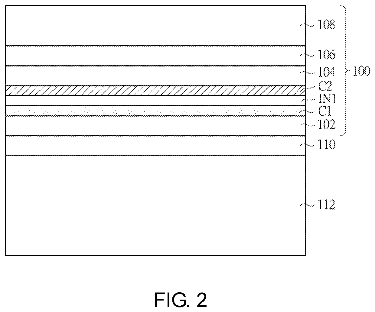
[0024]Referring to FIG. 2, it is a schematic cross-sectional view of a mutual capacitive touch panel according to the invention. A mutual capacitive touch panel 100 is employed to detect a position touched by a touch object and includes a first electrode layer C1, a second electrode layer C2 and an insulation layer IN1. The insulation layer IN1 is disposed between the first electrode layer C1 and the second electrode layer C2. The first electrode layer C1 and the second electrode layer C2 may be electrically insulated from each other by the insulation layer IN1, and the second electrode layer C2 is closer to the touch object for inputting commands than the first electrode layer C1. The touch object may be, for example, a finger or a stylus. In the present embodiment, the mutual capacitive touch panel 100 may further include a substrate 102, and the second electrode layer C2, the insulation layer IN1 and the first electrode layer C1 are formed sequentially on a first side of the subs...

fourth embodiment

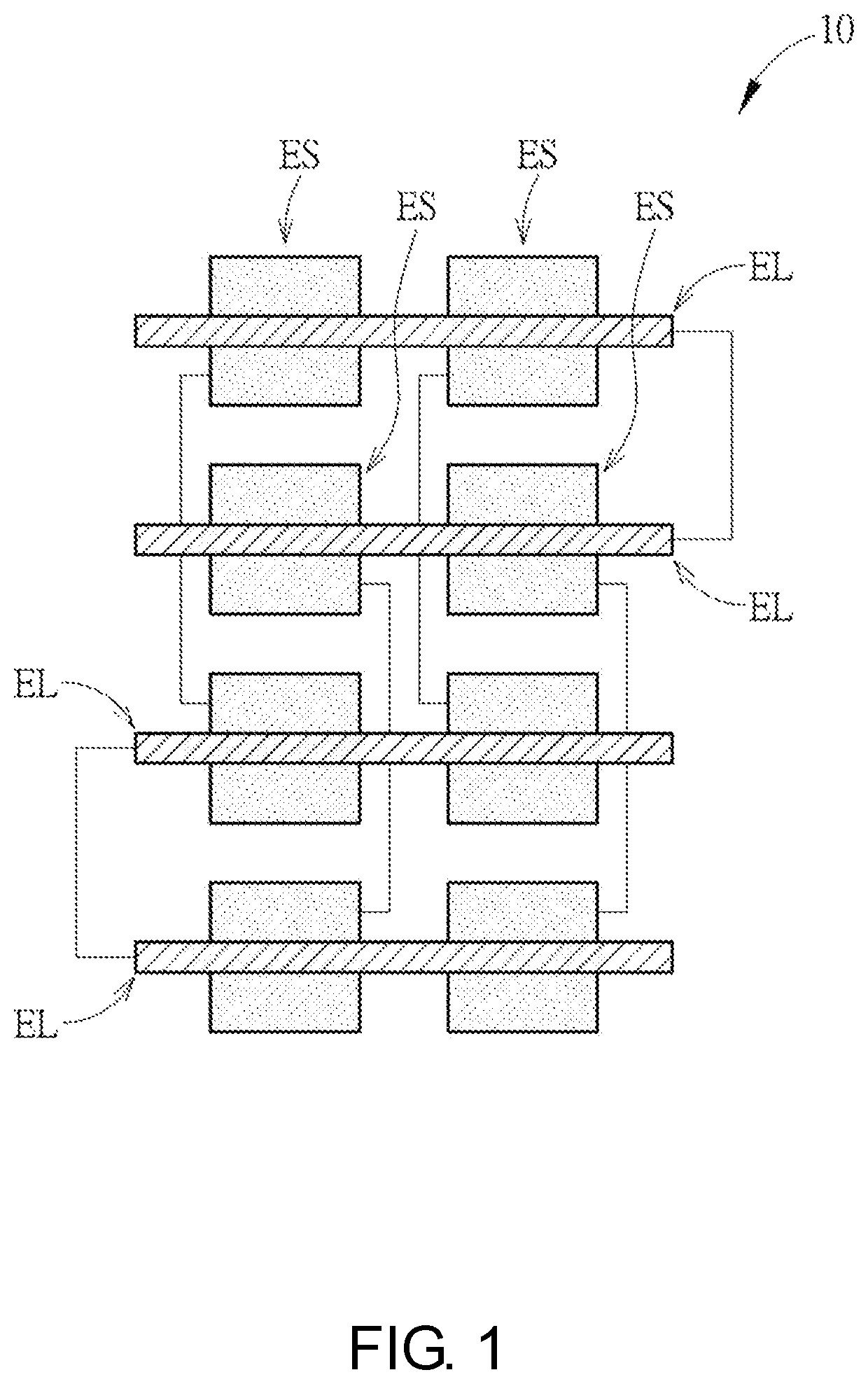
[0028]The aforementioned each embodiment uses a stack structure in which the insulation layer between the first electrode layer C1 and the second electrode layer C2 is thinner and thus, certainly has a greater background capacitance, such that it is necessary to redesign a shape of first electrodes of the first electrode layer and a shape of second electrodes of the second electrode layer, and top-view designs of the mutual capacitive touch panel of the invention will be further described below. Referring to FIG. 5, it is a schematic top view of a mutual capacitive touch panel according to the invention. In a mutual capacitive touch panel 400 provided by the present embodiment, a first electrode layer C11 includes a plurality of first electrode series ES1 which are separated and insulated from each other and a plurality of second electrode series ES2 which are separated and insulated from each other, wherein the first electrode series ES1 and the second electrode series ES2 respecti...

sixth embodiment

[0037]Referring to FIG. 7, it is a schematic top view of a mutual capacitive touch panel according to the invention. In a mutual capacitive touch panel 600 provided by the present embodiment, a first electrode layer C31 includes a plurality of first electrode series ES1 and a plurality of second electrode series ES2 respectively extending along the first direction D1, and each first electrode series ES1 corresponds to one of the second electrode series ES2. Each first electrode series ES1 includes a plurality of first electrodes E31 and a plurality of second electrodes E32 which are disposed in a touch area 600a of the mutual capacitive touch panel 600. In each of the first electrode series ES1, each first electrode E31 is electrically connected to each second electrode E32, and each first electrode E31 and its corresponding second electrode E32 are disposed abreast and form an electrode set EM3. Each of the second electrode series ES2 includes a plurality of third electrodes E33 el...


PUM

PropertyMeasurementUnit
thicknessaaaaaaaaaa
thicknessaaaaaaaaaa
thicknessaaaaaaaaaa

Abstract

A mutual capacitive touch panel includes a first electrode layer and a second electrode layer. The first electrode layer includes a plurality of first electrode series and a plurality of second electrode series. The second electrode layer includes a plurality of electrode strips, and each electrode strip crosses the first electrode series and the second electrode series. Each first electrode series includes a plurality of first electrodes and a plurality of second electrodes electrically connected with each other, and each first electrode and a corresponding one of the second electrodes are disposed abreast and form an electrode set. Each second electrode series includes a plurality of third electrodes electrically connected with each other, and each electrode set and each third electrode are arranged alternately along a direction.

Description

CROSS-REFERENCE TO RELATED APPLICATION[0001]This application claims the priority benefit of Taiwan application serial no. 107129198, filed on Aug. 22, 2018. The entirety of the above-mentioned patent application is hereby incorporated by reference herein and made a part of this specification.BACKGROUNDField of the Invention[0002]The invention relates to a mutual capacitive touch panel and more particularly, to a mutual capacitive touch panel having a dual-layer electrode structure.Description of Related Art[0003]A touch display device, as being composed of a display and a touch panel, can implement both of a touch function and a display function to feature in human-computer interaction and has been widely applied to electronic products, such as smart phones, GPS navigator systems, tablet PCs and notebook PCs. A mutual capacitive touch panel has advantages, such as high accuracy, multi-touch, high durability and high touch resolution and thus, has become a dominant touch technique in...

Claims


Application Information

Patent Timeline
Patent Type & Authority Patents(United States)
IPC IPC(8): G06F3/044
CPCG06F3/044G06F2203/04102G06F3/0445G06F3/0448
Inventor CHANG, HU-CHI
Owner ILI TECHNOLOGY CORPORATION
Why Eureka
Try Eureka