Fingerprint sensing module
- Summary
- Abstract
- Description
- Claims
- Application Information
AI Technical Summary
Benefits of technology
Problems solved by technology
Method used
Image
Examples
first embodiment
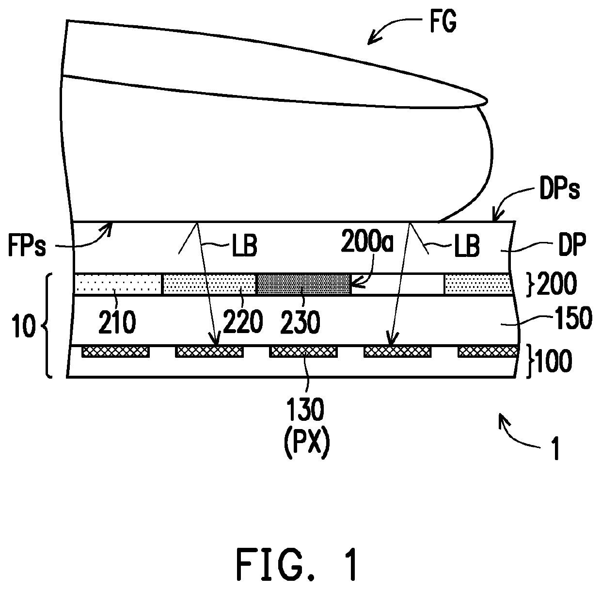
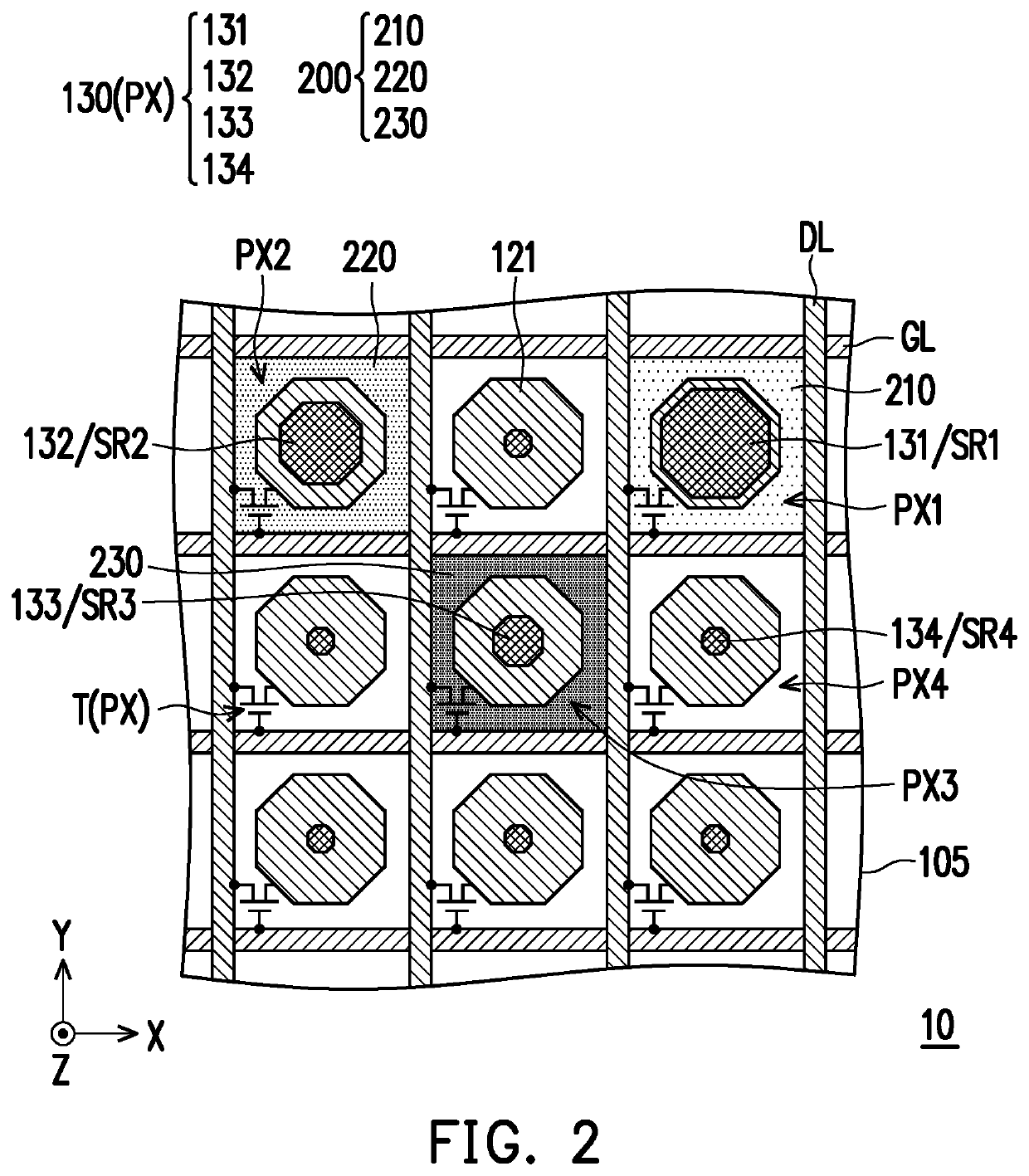
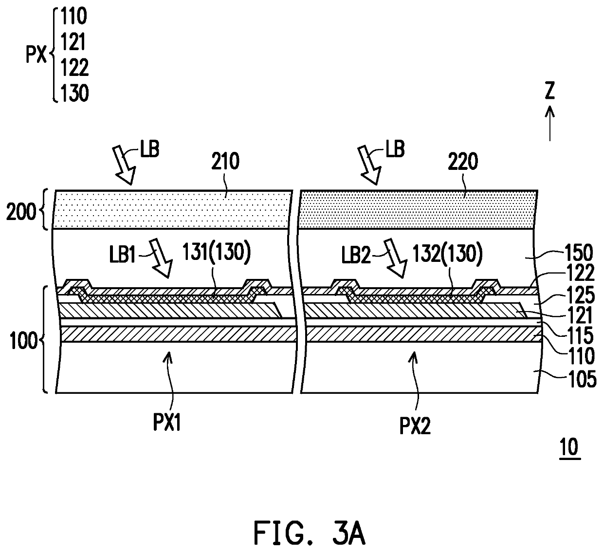
[0048]FIG. 1 is a schematic view of a fingerprint recognition device according to the disclosure. FIG. 2 is a schematic top view of a fingerprint sensing module in FIG. 1. FIGS. 3A and 3B are schematic cross-sectional views of the fingerprint sensing module in FIG. 2. FIG. 4 is a graph of quantum efficiency against wavelength of a photosensitive pattern in FIGS. 3A and 3B. FIG. 5 is a schematic cross-sectional view of the fingerprint sensing module in FIG. 3B with a modification. For clarity of presentation, illustrations of an insulation layer 115, a second electrode 122, and an insulation layer 150 in FIGS. 3A and 3B are omitted in FIG. 2.
[0049]With reference to FIG. 1, a fingerprint recognition device 1 includes a display panel DP and a fingerprint sensing module 10. The fingerprint sensing module 10 is, for example, disposed underneath the display panel DP (that is, on a side of the display panel DP away from a display surface DPs), and the display panel DP is a self-luminous di...
second embodiment
[0064]FIG. 6 is a schematic top view of a fingerprint sensing module according to the disclosure. FIGS. 7A and 7B are schematic cross-sectional views of the fingerprint sensing module in FIG. 6. For clarity of presentation, the illustrations of the insulation layer 115, the second electrode 122, and the insulation layer 150 in FIGS. 7A and 7B are omitted in FIG. 6.
[0065]With reference to FIGS. 6 to 7B, a difference between a fingerprint sensing module 11 of the embodiment and the fingerprint sensing module 10 in FIG. 2 is that the fingerprint sensing module 11 further includes a light shielding pattern layer 140 disposed on the multiple photosensitive patterns 130. In the embodiment, the light shielding pattern layer 140 includes multiple light shielding patterns disposed corresponding to multiple photosensitive pixels PXA, and the light shielding patterns have openings of four different sizes. A material of the light shielding pattern layer 140 may include a metal, a black resin, o...
third embodiment
[0068]FIG. 8 is a schematic top view of a fingerprint sensing module according to the disclosure. With reference to FIG. 8, a difference between a fingerprint sensing module 11A of the embodiment and the fingerprint sensing module 11 in FIG. 6 is that an opening structure of a portion of light shielding patterns of a light shielding pattern layer 140A is different from an opening structure of a portion of the light shielding patterns of the light shielding pattern layer 140. For example, in the embodiment, the light shielding pattern layer 140A defines an opening 142b of a light shielding pattern 142A of a photosensitive region SR2B of a photosensitive pixel PX2B to be composed of multiple separate sub-openings, and the sub-openings of the light shielding pattern 142A are arranged at intervals in the X direction. Similarly, the light shielding pattern layer 140A defines an opening 143b of a light shielding pattern 143A of a photosensitive region SR3B of a photosensitive pixel PX3B t...
PUM
| Property | Measurement | Unit |
|---|---|---|
| quantum efficiency | aaaaa | aaaaa |
| photosensitive | aaaaa | aaaaa |
| quantum efficiency | aaaaa | aaaaa |
Abstract
Description
Claims
Application Information
 - R&D
- Intellectual Property
- Life Sciences
- Materials
- Tech Scout
- Unparalleled Data Quality
- Higher Quality Content
- 60% Fewer Hallucinations
Browse by: Latest US Patents, China's latest patents, Technical Efficacy Thesaurus, Application Domain, Technology Topic, Popular Technical Reports.
© 2025 PatSnap. All rights reserved.Legal|Privacy policy|Modern Slavery Act Transparency Statement|Sitemap|About US| Contact US: help@patsnap.com


