Method and system for representing dependencies in a financial plan

a financial plan and dependency technology, applied in the field of computer systems and application programs, can solve the problems of cumbersome financial plan creation, difficult to make changes to the plan, and financial planning software does not capture these relationships, so as to quickly see how their financial plan would be affected

Inactive Publication Date: 2008-04-22
MICROSOFT TECH LICENSING LLC
View PDF8 Cites 13 Cited by
  • Summary
  • Abstract
  • Description
  • Claims
  • Application Information

AI Technical Summary

Problems solved by technology

Although such a relationship is implicitly understood by a user, financial planning software does not capture these relationships.
There are two main problems with this approach.
A first problem it that this approach makes it cumbersome to create the financial plan, because the user must be diligent about entering exactly the same dates and / or amounts on separate variables.
Secondly, after a first draft of the plan is created, it is difficult to make changes to the plan because the user must manually maintain the implicit relationships between objects.
As can be readily appreciated, more complex events such as retirement (e.g., wherein income and contributions to a savings plan cease, monthly commuting expenses change, and so forth) may require concurrent updates to many variables, of which even a careful user can easily lose track.
Moreover, present financial planning software does not make it easy for the user to see the impact of removing a financial event from their plan.
Still another drawback to existing financial planning software is that it is separated from the user's real day-to-day financial transactions, even for users that use an electronic “checkbook” type of software program for tracking day-to-day transactions.
The planning software thus relies on the user to make appropriate updates, which tends to make a financial plan quickly outdated for many users.

Method used


Image

  • Method and system for representing dependencies in a financial plan
  • Method and system for representing dependencies in a financial plan
  • Method and system for representing dependencies in a financial plan

Examples


Embodiment Construction

Exemplary Operating Environment

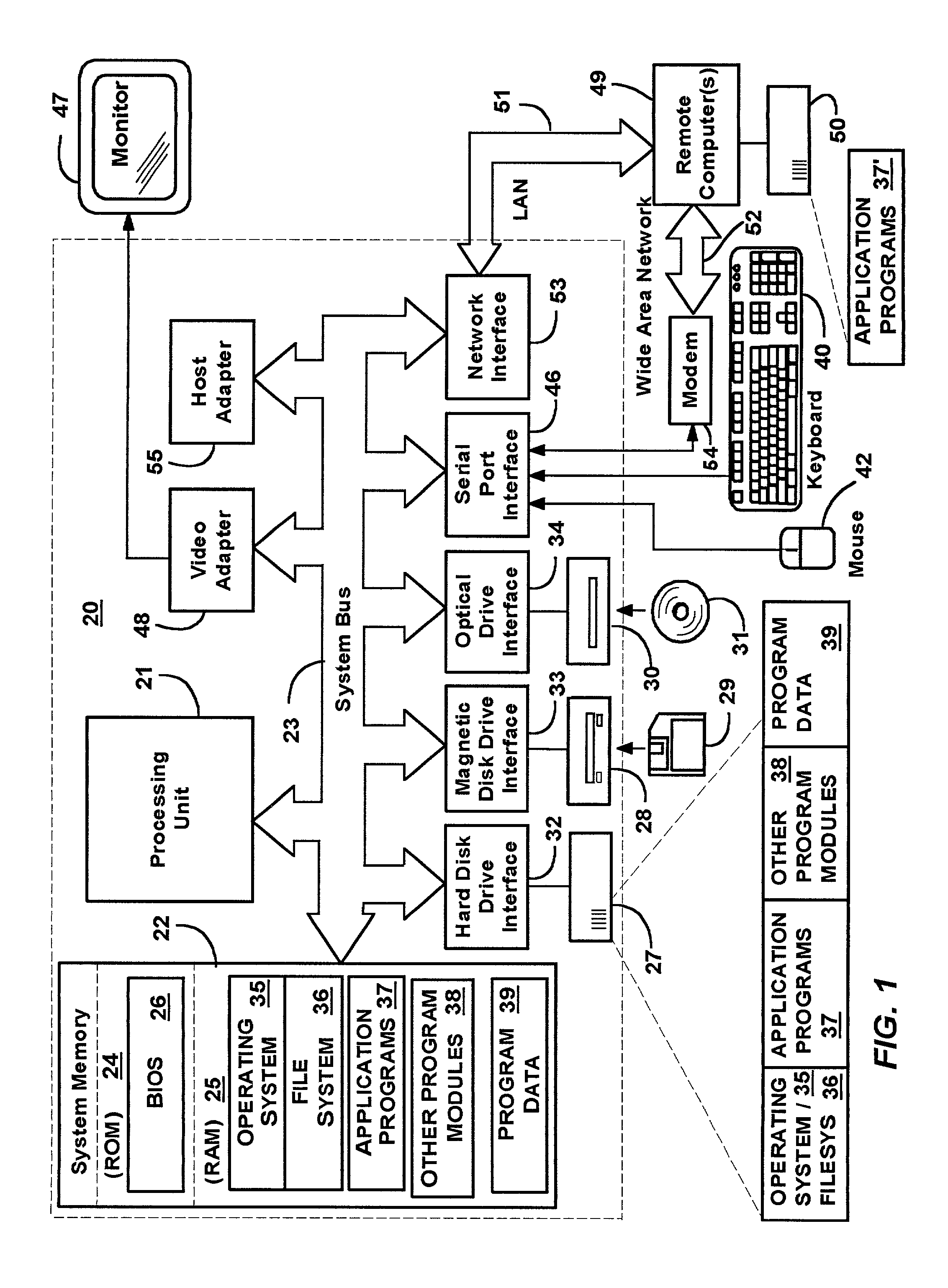
[0020]FIG. 1 and the following discussion are intended to provide a brief general description of a suitable computing environment in which the invention may be implemented. Although not required, the invention will be described in the general context of computer-executable instructions, such as program modules, being executed by a personal computer. Generally, program modules include routines, programs, objects, components, data structures and the like that perform particular tasks or implement particular abstract data types. Moreover, those skilled in the art will appreciate that the invention may be practiced with other computer system configurations, including hand-held devices, multi-processor systems, microprocessor-based or programmable consumer electronics, network PCs, minicomputers, mainframe computers and the like. The invention may also be practiced in distributed computing environments where tasks are performed by remote processing devices ...


PUM


Abstract

A method and system architecture for managing the objects used in simulating a financial-type plan. Objects are hierarchically arranged with fields therein that specify financial information including dates, rates, amounts of objects and strings. The fields may be selectively chosen to be dependent on the dates, rates or amounts of other objects, whereby any change made to the value in one field is automatically linked to any related fields. Each field alternatively be given a fixed value, and fields, whether fixed or referenced to another field, may be accompanied by an adjustment field that offsets the value in the field. Objects may be grouped in packages, and objects and packages may be selectively enabled and disabled, whereby such objects will be included or omitted from the financial simulation calculations without having to reenter or delete those objects. The objects used in the financial planning may be synchronized with financial information from another program so as to use more updated amounts.

Description

FIELD OF THE INVENTION[0001]The invention relates generally to computer systems and application programs, and more particularly to computer software and data used in developing plans such as financial plans.BACKGROUND OF THE INVENTION[0002]To accurately model a person's or a family's financial plan requires managing a large number of variables. For example, to create a financial plan that is meaningful, the user needs to provide a lot of current information such as salary, debt and savings, and also needs to specify many future financial events, such as paying for a child's college education, getting a raise, contributing to a savings plan, and retiring. Present financial planning software uses the input information to develop a financial plan, typically by running a simulation with the input information and outputting whatever results.[0003]Many financial events may be dependent on other financial events. For example, a user may plan to buy a boat as soon as a car is paid off. Alth...

Claims


Application Information

Patent Timeline
Patent Type & Authority Patents(United States)
IPC IPC(8): G06Q40/00
CPCG06Q20/10G06Q20/102G06Q40/00G06Q40/025G06Q40/04G06Q40/06G06Q40/03
Inventor MAGARAM, JUSTIN B.PARLIN, DAVID R.
Owner MICROSOFT TECH LICENSING LLC
Why Eureka
Try Eureka