Cutters for downhole cutting devices

a cutting device and downhole technology, applied in the direction of earthwork drilling, well accessories, borehole/well accessories, etc., can solve the problems of cutter loosening, cutter breaking off, cutters may become loose, etc., and achieve the effect of less interstitial space and increased bond area

Active Publication Date: 2008-04-29
BAKER HUGHES INC
View PDF8 Cites 72 Cited by
  • Summary
  • Abstract
  • Description
  • Claims
  • Application Information

AI Technical Summary

Benefits of technology

[0009]The cutters of the present invention provide advantages for attachment to a cutter arm or blade. Bond area is increased. Therefore, the cutters remain in place more securely. Also, placement of the rounded, rectangular cutters on a cutting arm results in less interstitial space between cutters. In return, this results in less extrusion of ductile metals into the interstitial spaces and less resultant damage to the arm or blade carrying the cutters.

Problems solved by technology

However, the use of circular cutters has some inherent drawbacks when used to cut through metallic tubular members.
First, there is a small amount of bond area between the cutter and the arm or blade upon which the cutter is mounted.
During cutting, the cutters may become loose and break off of the cutting arm.
Additionally, the geometry of circular cutters results in a significant amount of interstitial space between cutters.
This is detrimental, particularly, when the cutter is cutting through metal that is ductile, such as casing containing high amounts of chrome and / or nickel.
These materials will enter the interstitial spaces and erode away the cutting arm during cutting.
In the instance of a rotary cutting mill, the presence of large interstitial spaces also presents a significant problem because of the cutting pattern provided by the mill.
This repeated pattern of cutting will result in grooves in the cut material and undesirably force the uncut portions of the material lying between the grooves into the interstitial spaces.
However, these half-cutters have little bonding area and are prone to breaking off.
Mandrel cutters are problematic because they require the use of cutting portions that are very small and narrow in order to effectively cut through the mandrel.
The limitation on the size of the cutting portion exacerbates the bonding area problem described above.

Method used


Image

  • Cutters for downhole cutting devices
  • Cutters for downhole cutting devices
  • Cutters for downhole cutting devices

Examples


Embodiment Construction

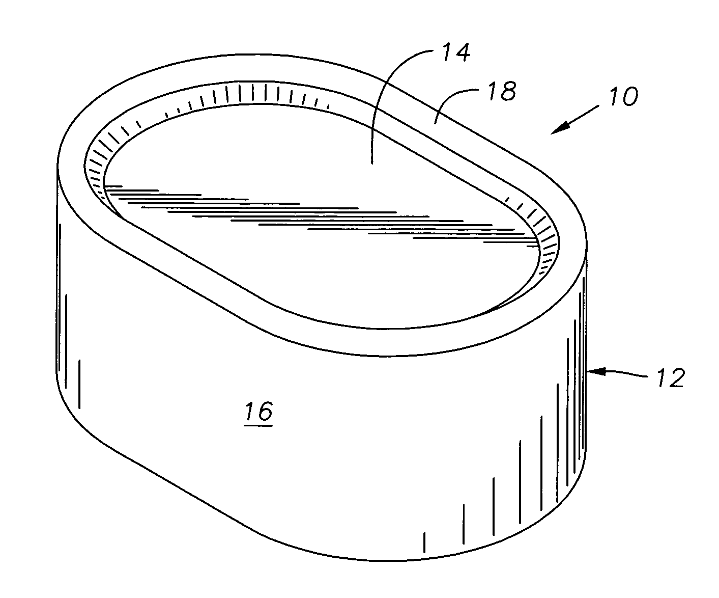
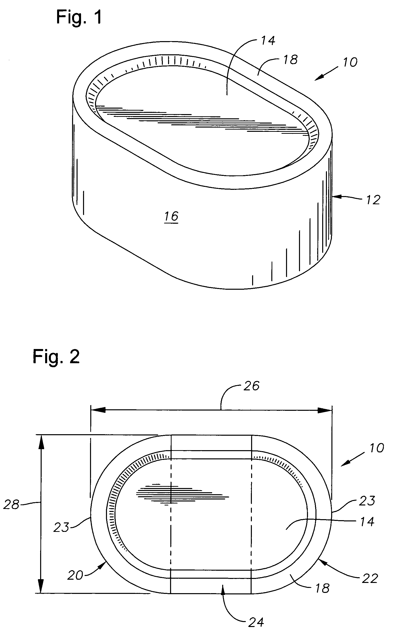
[0018]FIGS. 1 and 2 depict an exemplary cutter 10 that is constructed in accordance with the present invention. The cutter 10 has a body 12 that is preferably formed of hardened carbide. However, the cutter 10 might also be formed of PDC, as is known in the art, or another substance suitable for use in downhole cutting. The body 12 features a cutting face 14 and a sidewall 16. Preferably, the cutter 10 features a raised chip-breaking edge 18 that is located proximate the outer circumference of the cutting face 14. When considered from the plan view offered by FIG. 2, the body 12 of the cutter 10 is generally made up of three sections: two end sections 20, 22 with end walls 23 that are semi-circular in shape, and a generally rectangular central section 24 that interconnects the two end sections 20, 22 to result in a rounded, rectangular “lozenge” shape for the cutter 10.

[0019]FIG. 2 also illustrates the currently preferred dimensions for the cutter 10. The cutter 10 has an overall le...


PUM


Abstract

Improved cutter design as well as an improved design for downhole cutters, such as mandrel cutters and rotary cutter mills. A cutter is described with a rectangular, rounded “lozenge” shape. The cutter presents a cross-sectional cutting area having a pair of curvilinear end sections and an elongated central section. Preferably, the overall length of the cutter is 1.5 times the width. The cutter may also include a raised cutter edge for chip breaking during cutting.

Description

BACKGROUND OF THE INVENTION[0001]1. Field of the Invention[0002]The invention relates generally to the design and use of cutters for the cutting arms and blades of underreamers, mills and other downhole tools.[0003]2. Description of the Related Art[0004]Rotary cutting mills and mandrel cutters are devices that are incorporated into a drill string and used to cut laterally through metallic tubular members, such as casing on the sides of a wellbore, liners, tubing, pipe or mandrels. Mandrel cutters are used to create a separation in metallic tubular members. Cutting mills are tools that are used in a sidetracking operation to cut a window through surrounding casing and allow drilling of a deviated drill hole. On conventional tools of this type, numerous small individual cutters are attached to multiple arms or blades that are rotated about a hub. Most conventional cutters present a circular cutting face. Other conventional cutter shapes include square, star-shaped, and trapezoidal, al...

Claims


Application Information

Patent Timeline
Patent Type & Authority Patents(United States)
IPC IPC(8): E21B10/46
CPCE21B10/5673E21B29/06
Inventor STOWE, CALVINMCNICOL, JAMES
Owner BAKER HUGHES INC
Why Eureka
Try Eureka