Combined rock-embedding pile and its construction method

A construction method and combined pile technology, applied in sheet pile wall, foundation structure engineering, construction and other directions, can solve the problems of necking, cavity and sediment interlayer, severe vibration, and high technical requirements for operation, and achieve good economic benefits and quality. Guaranteed, extubation speed increase, accurate calculation effect

Inactive Publication Date: 2002-12-25
LIJI ENG
View PDF1 Cites 21 Cited by
  • Summary
  • Abstract
  • Description
  • Claims
  • Application Information

AI Technical Summary

Problems solved by technology

The disadvantages of this method are: first, the construction noise is large and the vibration is severe; second, the pile body is easily damaged or weakened under the violent and continuous impact of the piling hammer; The ability is poor. When some piles of the foundation have to be located on the local hard soil layer, it is easy to cause uneven settlement and inclination of the building. Fourth, the deeper the bearing layer, the greater the energy of the pile hammer required, which will give the piling machine The production of
Construction costs also increase accordingly
[0005] 2. As the grouting material of the protective layer, it may have to face loose soil layer and groundwater before hardening, and there is no steel skeleton in it, so the construction quality is easily affected by the speed of pulling out the temporary casing, the soil quality and the flow of groundwater. Quality problems such as necking, voids and sediment interlayers
[0006] In the design of some composite piles, although prefabricated piles and cast-in-place concrete parts are also included, their bearing mechanism is still the same as that of traditional bored piles, that is, the load is transmitted by the local pressure of the pile bottom and the contact level of the rock. Typical end-on piles are only partly replaced by prefabricated concrete piles, see JP-127054, it is always difficult to avoid the influence of sediment on the quality of piles
Because the strength of concrete is usually greater than that of rock, if the full bearing capacity of the pile body is to be exerted, the bottom must be expanded, and the cost of the machinery used for bottom expansion is high, the operation technology requirements are high, and pipe sticking accidents are prone to occur, the actual bottom expansion size also difficult to control
The positioning of the prefabricated pile sections was also very difficult as there were no reinforcements extending straight to the rock face

Method used


Image

  • Combined rock-embedding pile and its construction method
  • Combined rock-embedding pile and its construction method
  • Combined rock-embedding pile and its construction method

Examples


Embodiment Construction

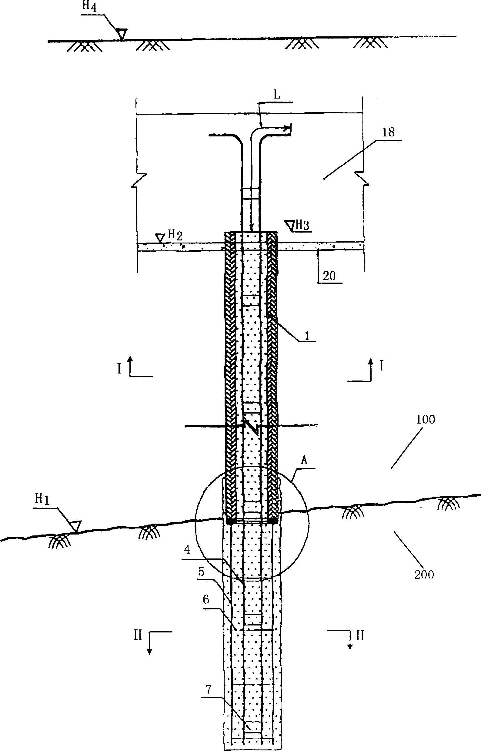
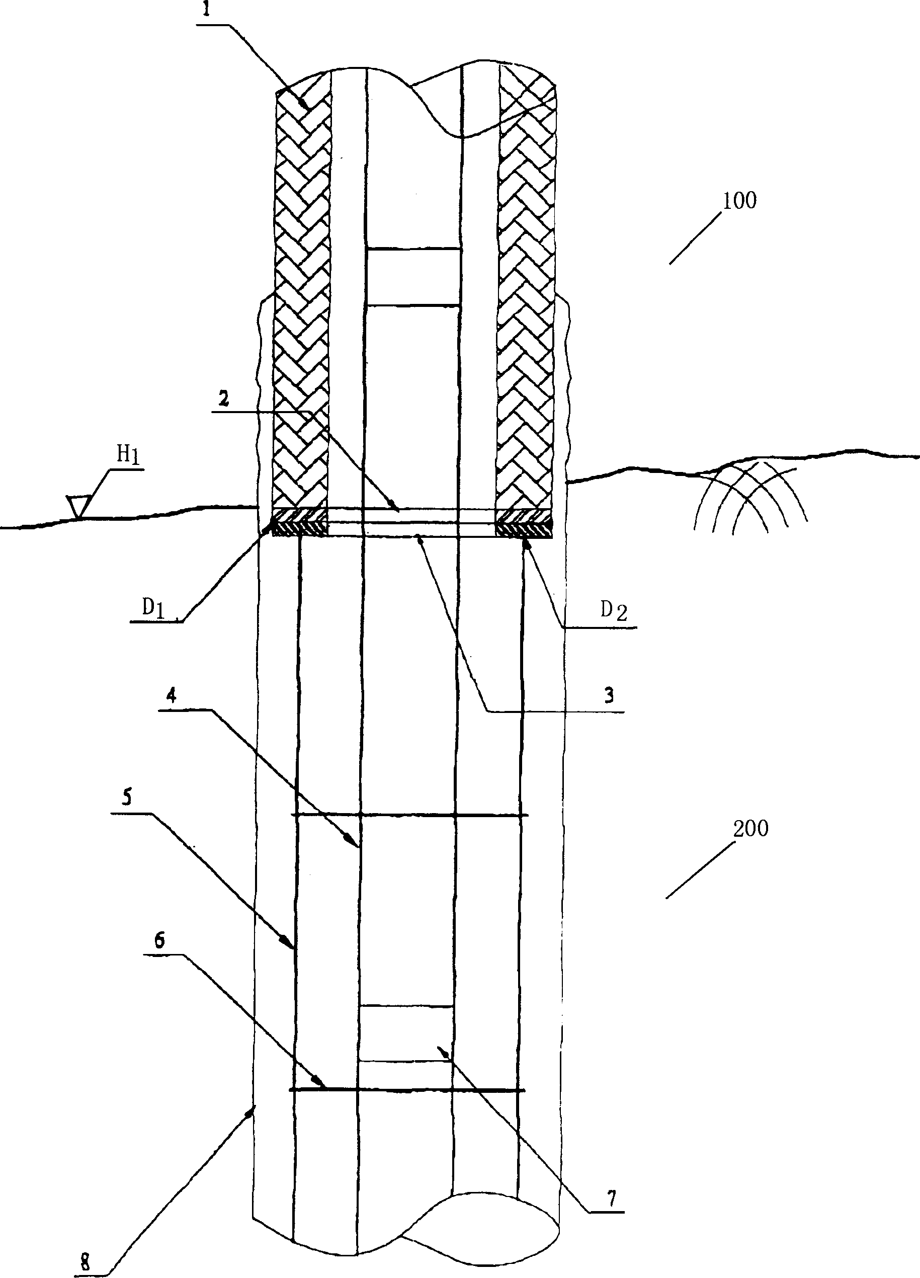
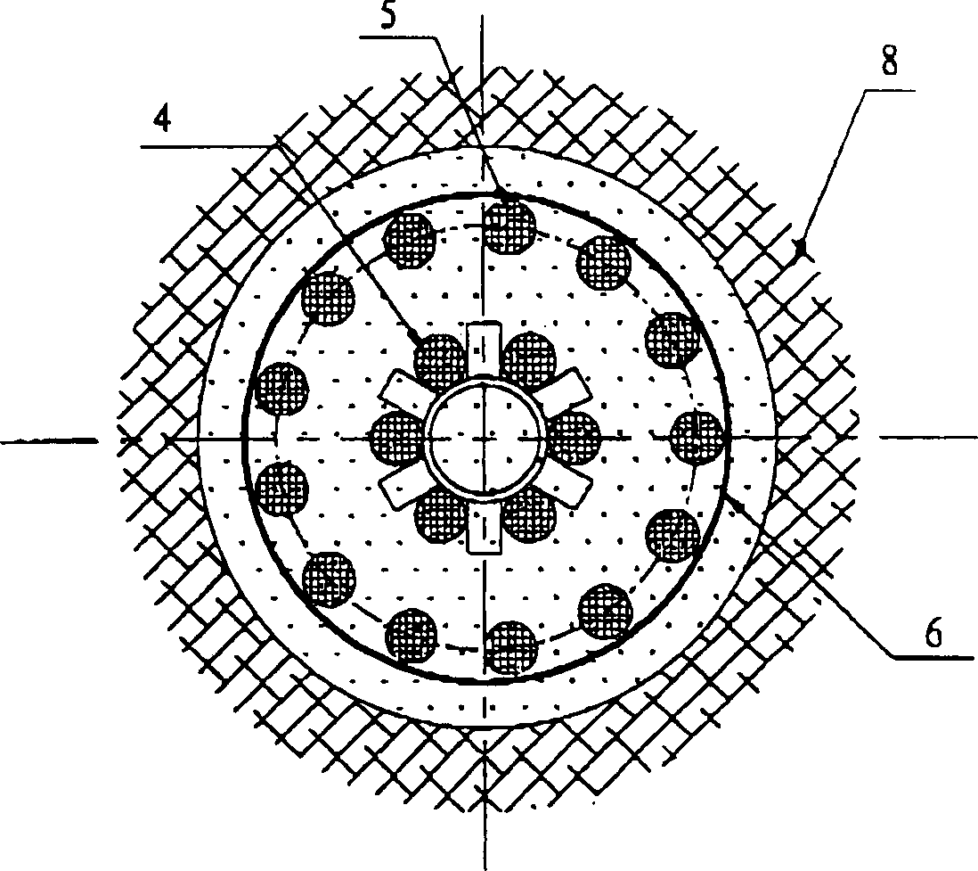
[0061] exist figure 1 with figure 2 The detailed internal structure of the first embodiment of the present invention, Type 1, is shown in . exist figure 1 Among them, the pile body is set in the soil layer 100 and the rock layer 200. According to the design requirements of the pile body, the rock top surface elevation H1, the pile cap bottom elevation H2, the pile head design elevation H4, and the construction surface ground elevation H4 are set accordingly, and Pile cap 18, cushion layer 20 and anchorage length L. There is an end plate 2 at the lower end of the concrete pipe 1, and below the end plate 2 is a reinforcement cage end plate 3, a plurality of main reinforcement bars 4 that run through the entire length of the pile body, and a plurality of reinforcement bars 5 that are only arranged in the rock hole. figure 1 , figure 2 , Figure 3, it can be seen that the distribution circle of the main reinforcement 4 is smaller than that of the reinforcement 5. The spacer ...


PUM


Abstract

A combined pile embedded in rock is constructed through prefabricating reinforced concrete pipe or other pile with reinforcing bars used as the load bearing member in soil layer, embedding the reinforced concrete member or steel member with reinforcing bars in the drilled hole in rock, and grouting in-situ. At least one group of reinforcing bars passes through said member and cast inside it for bearing pressure or pull and improving the integrity of whole pile. Its advantages are high load-bearing power, simple structure and low cost.

Description

technical field [0001] The invention relates to a pile used as a deep foundation of a building, in particular to a combined pile which relies on the bonding force between grouting material, prefabricated pile and the inner wall of a rock hole to gradually spread the load to the bearing rock layer along the vertical direction and its construction method. Background technique [0002] The prefabricated piles used in the foundation of buildings have always been connected one by one by a pile driver on site with prefabricated reinforced concrete piles or section steel piles, and the soil is squeezed into the design depth. The bearing capacity of the force layer is used to support the pile head load, such as US patent US 4,199,277. The disadvantages of this method are: first, the construction noise is large and the vibration is severe; second, the pile body is easily damaged or weakened under the violent and continuous impact of the piling hammer; The ability is poor. When some ...

Claims


Application Information

Patent Timeline
Patent Type & Authority Applications(China)
IPC IPC(8): E02D5/50
Inventor 张向东
Owner LIJI ENG
Why Eureka
Try Eureka