Sprayer with pivotal wing booms having forward and reverse breakaway and folded X-shaped transport position

a technology of pivotal wing booms and wing booms, which is applied in the field of spraying, can solve the problems of affecting the stability unable to pass through restricted height spaces, and unable to strike low lying branches, so as to prevent the damage of the spraying machin

Active Publication Date: 2008-04-29
TORO CO THE
View PDF12 Cites 49 Cited by
  • Summary
  • Abstract
  • Description
  • Claims
  • Application Information

AI Technical Summary

Benefits of technology

[0014]Yet another aspect of this invention relates to a sprayer for spraying a liquid onto an upwardly facing surface. The sprayer is carried on a vehicle for moving the sprayer over the surface. The sprayer comprises a center boom carried on the vehicle. A pair of wing booms are pivotally mounted to opposite ends of the center boom. A plurality of downwardly facing spray nozzles are carried on the center and wing booms for spraying liquid downwardly onto the upwardly facing surface. Laterally outermost ends of the wing booms have rounded front and rear corners to prevent damage to trees.

Problems solved by technology

When the wing booms fold vertically, they extend upwardly quite high which can lead to various problems.
For example, if the wing booms are long, they can extend so high when folded up that they would strike low lying branches or be unable to pass through restricted height spaces, such as tunnels.
Another problem with known sprayers is the possibility of damage to the folded wing booms due to impact with low-overhead objects while the wing booms are in their transport positions during a transport event.
This is obviously not desirable.
Another problem with known sprayers is the possibility of damage when the wing booms are in their horizontal, extended spraying position.
Because the wing booms stick outwardly well beyond the sides of the vehicle, and because it can be difficult to judge the clearance between the ends of the wing booms and an obstacle, it is not unusual for the operator to drive the ends of the wing booms into an obstacle, such as a tree or post.
This impact can damage the wing boom and / or the obstacle struck by the wing boom.
In the case of a tree, the wing boom can scar or damage the tree in such a way that its appearance is permanently marred or its health impaired significantly enough to require replacement of the tree.
Either result is unfortunate.
However, this is most often done only if the wing boom strikes an obstacle when the vehicle is moving forwardly.
Obviously, this is a time consuming and onerous process since the operator must stop the vehicle, dismount the vehicle, reset the wing boom, and then remount and start the vehicle to resume spraying.
Finally, to the extent that the obstacle that causes the wing boom to breakaway is a tree or plant, there will be some contact between the wing boom and the tree or plant even if the wing boom breaks away.
The tree or plant can still be damaged as result of this contact.

Method used


Image

  • Sprayer with pivotal wing booms having forward and reverse breakaway and folded X-shaped transport position
  • Sprayer with pivotal wing booms having forward and reverse breakaway and folded X-shaped transport position
  • Sprayer with pivotal wing booms having forward and reverse breakaway and folded X-shaped transport position

Examples


Embodiment Construction

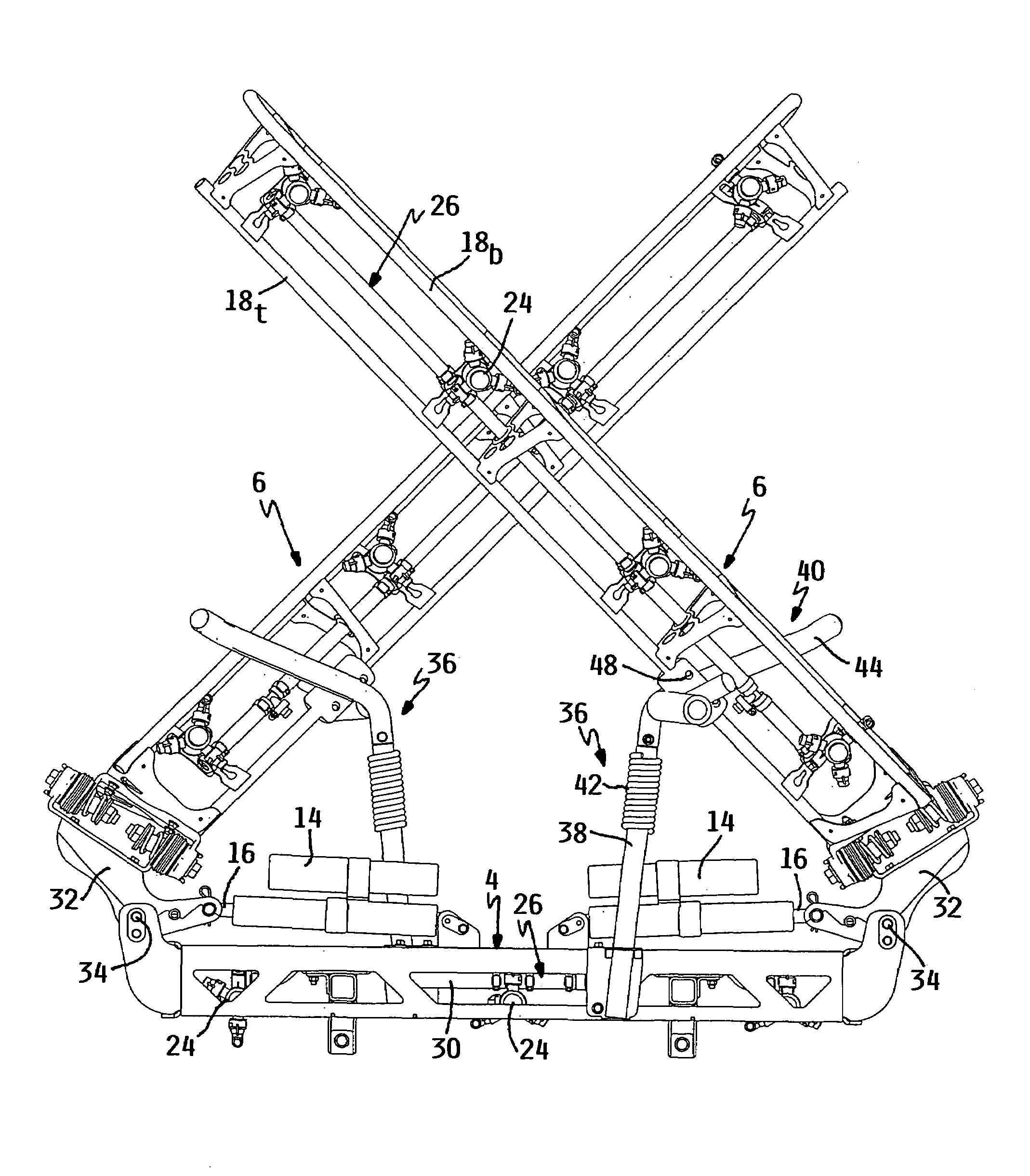
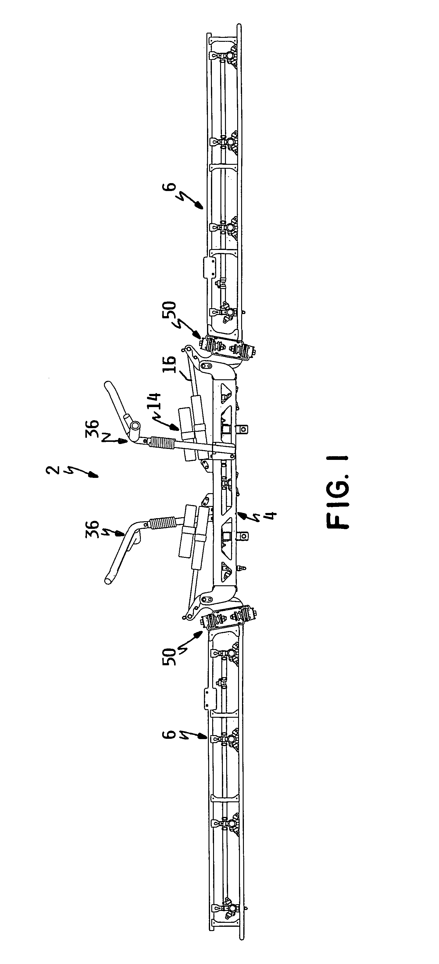
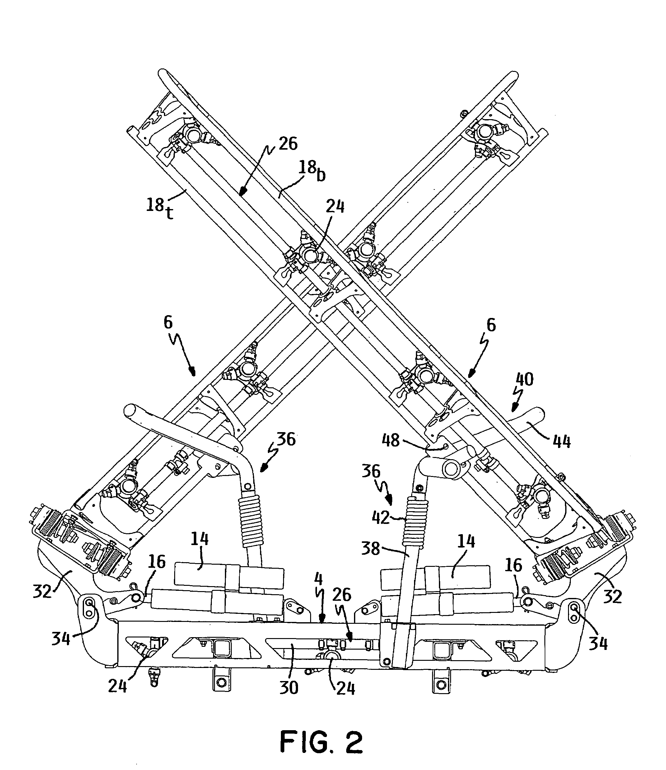
[0031]One embodiment of a sprayer according to this invention is illustrated as 2 in FIG. 1. Sprayer 2 comprises a center boom 4 and a pair of pivotal wing booms 6. A laterally inner end of each wing boom 6 is pivotally coupled to a laterally outer end of center boom 4. Each wing boom pivots relative to center boom 4 about two pivot axes, namely a fore-and-aft extending lift pivot axis x and a substantially vertical but somewhat inclined breakaway pivot axis y. See FIG. 3.

[0032]Center boom 4 carries a pair of hitch arms or mounts 8 that allow sprayer 2 to be carried on a transport vehicle (not shown), such as a tractor, mower or utility vehicle. The vehicle carries sprayer 2 over the ground in a forward direction F and in a reverse direction R as indicated by the arrows F and R in FIG. 5. The vehicle will also carry a tank (not shown) of a liquid, such as a fertilizer, insecticide, and herbicide. This liquid will be pumped out of the tank and sprayed onto the ground through a plural...


PUM


Abstract

This invention relates to a sprayer having a center boom and pivotal wing booms. The wing booms can be pivoted from an extended spray position to an elevated transport position by lifting and lowering each wing boom about a longitudinal lift pivot axis. In addition, each wing boom can bi-directionally breakaway relative to the center boom by virtue of a breakaway pivot arranged between the lift pivot axis and the innermost end of the wing boom. The breakaway pivot has at least one pair of nested cams that are biased into their nested condition by at least one spring. The center boom carries a pair of support cradles that direct or cam one wing boom forwardly and the other wing boom rearwardly as the wing booms are lifted into the transport position such that the wing booms form an X-shape relative to one another. The support cradles are partially flexible to allow the wing booms to release from the cradles if they strike an obstruction.

Description

TECHNICAL FIELD[0001]This invention relates to a sprayer for spraying liquids, such as liquid fertilizer, insecticides, herbicides and the like, for horticultural purposes. More particularly, this invention relates to a sprayer having a center boom and a pair of pivotal wing booms.BACKGROUND OF THE INVENTION[0002]Vehicle mounted sprayers of various types are well known for spraying liquids used for growing and maintaining a healthy turf surface or for other horticultural purposes. Such vehicle mounted sprayers are particularly useful for spraying large turf areas that would be too time consuming to treat with handheld or walk behind sprayers.[0003]In order to increase the width of the spray, many vehicle mounted sprayers include a center boom that is fixed to the vehicle. A pair of wing booms are pivotally attached to each end of the center boom. In a spraying position, the wing booms are extended horizontally outward from and laterally aligned with the center boom so that the spray...

Claims


Application Information

Patent Timeline
Patent Type & Authority Patents(United States)
IPC IPC(8): B05B1/20A01C23/02E01C19/17E01H3/02
CPCA01C23/008A01M7/0075A01M7/0078B05B1/1645
Inventor SOSNOWSKI, TIMOTHY P.BISSON, ROBERT J.ELLSON, BART T.NORLANDER, DAVID J.
Owner TORO CO THE
Why Eureka
Try Eureka