Exhaust control valve for internal combustion engine

a technology of exhaust control valve and internal combustion engine, which is applied in the direction of non-mechanical valves, output power, mechanical apparatus, etc., can solve the problems of no main exhaust valve at all, high system cost, and complex design of the exhaust valve, and achieve the greatest possible peak torque, small installed size, and simple construction

Inactive Publication Date: 2008-05-06
BRP ROTAX
View PDF18 Cites 12 Cited by
  • Summary
  • Abstract
  • Description
  • Claims
  • Application Information

AI Technical Summary

Benefits of technology

[0014]Other aspects of embodiments of the invention allow a relatively small installation space, a simple mounting arrangement and a reliable operation of the exhaust control valve assembly.
[0049]If the main exhaust slide valve and at least one auxiliary exhaust slide valve are adjusted in directions that the parallel to each other, it becomes much simpler to couple the main exhaust slide valve and at least one auxiliary exhaust slide valve. The main exhaust slide valve and the least one auxiliary exhaust slide valve can, in an advantageous manner, be actuated by the common adjusting device, for example, against the action of a spring, it being possible, in principle, to make the spring act in the direction of the operating position or the starting position.

Problems solved by technology

One disadvantage of this known exhaust period control system is its technically complex design.
However, this design incorporates no main exhaust valve at all.
This system is expensive and takes up a great deal of space.

Method used


Image

  • Exhaust control valve for internal combustion engine
  • Exhaust control valve for internal combustion engine
  • Exhaust control valve for internal combustion engine

Examples


Embodiment Construction

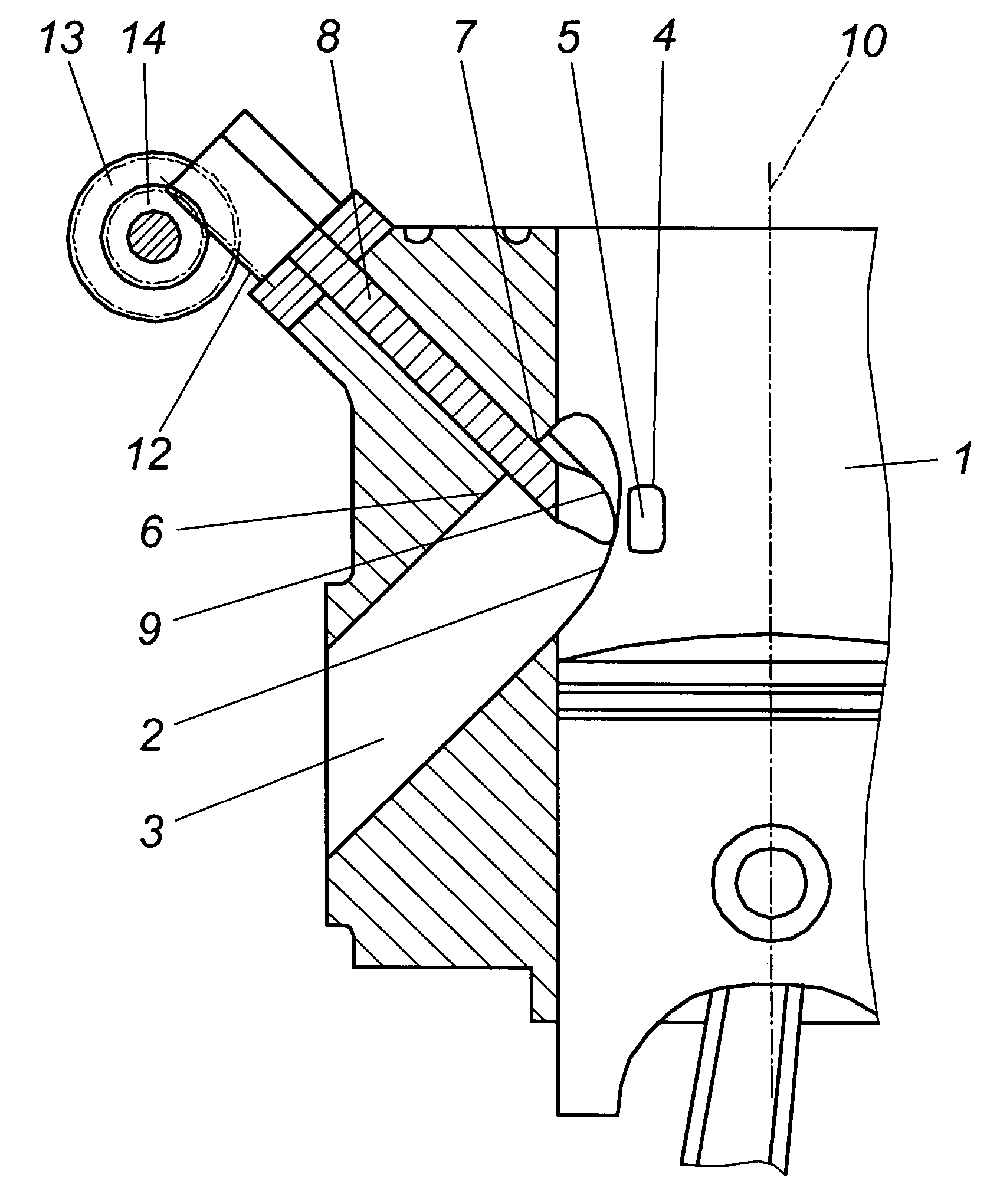
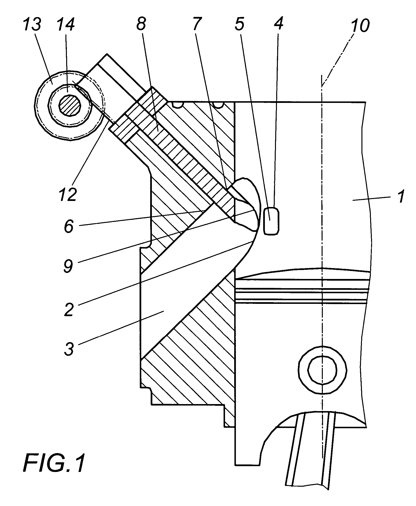
[0062]Referring to FIGS. 1 to 4, the cylinder 1 of a two-cycle internal combustion engine has an exhaust passage 3 that adjoins a main exhaust outlet 2 and, located symmetrically to this main exhaust outlet 2, lateral auxiliary exhaust outlets 4 that are connected to the exhaust passage 3 through of lateral channels 5. The wall 6 of the exhaust passage 3 that is proximate to the cylinder head forms a passage opening 7 for the main exhaust slide valve 8, which has at its unattached face end a control edge 9 that conforms to the cylinder bore. This main exhaust slide valve 8 can move between a position in which it is withdrawn into the passage opening 7 and a position in which it is advanced against the cylinder jacket, at an acute angle to the cylinder axis 10 and almost perpendicular to the wall 6 of the exhaust passage 3 that is proximate to the cylinder head.

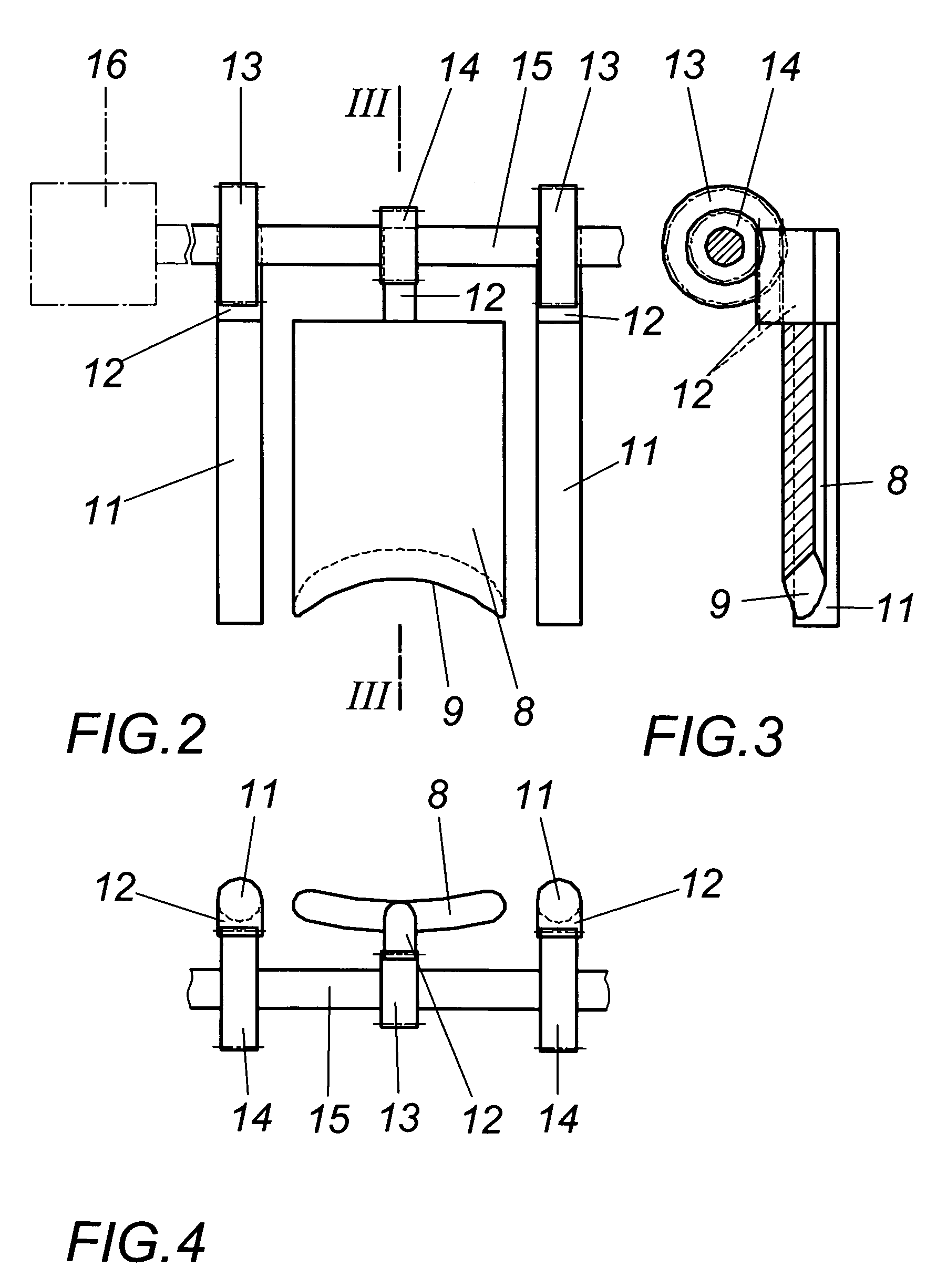
[0063]Receiving bores for the auxiliary exhaust slide valves 11 that are associated with the lateral channels 5 and which ar...


PUM


Abstract

An exhaust valve assembly for a two stroke internal combustion engine having a cylinder with at least one main exhaust port and one auxiliary exhaust port is disclosed. The assembly comprises a main exhaust valve for at least partially closing the main exhaust port, an auxiliary exhaust valve for at least partially closing the auxiliary exhaust port, an actuator for actuating the main exhaust valve and the auxiliary exhaust valve, the actuator including a rotary shaft having a first gear and a second gear, the rotary shaft being operatively connected to the main exhaust valve via the first gear, the rotary shaft being operatively connected to the auxiliary exhaust valve via the second gear, an electric motor operatively connected to the rotary shaft for rotating the rotary shaft.

Description

[0001]The present invention claims priority to U.S. Provisional Application Ser. No. 60 / 515,694, which was filed on Oct. 31, 2003, the entirety of which is hereby incorporated into the present application by reference.BACKGROUND OF THE INVENTION[0002]1. Field of the Invention[0003]The present invention relates to a exhaust control valve assembly of a two stroke internal combustion engine. More particularly, the invention relates to a technically efficient exhaust control assembly wherein both the main exhaust control valve and the at least one auxiliary exhaust control valve can be controlled by only one actuator.[0004]2. Discussion of the Related Art[0005]As is generally known two-stroke (often referred also as two-cycle) engines generally have exhaust and intake ports in the side walls of a cylindrical chamber. The cylindrical chamber and its side walls are usually referred to simply as a cylinder. While the intake ports feed air into the cylinder, the exhaust ports guide burned g...

Claims


Application Information

Patent Timeline
Patent Type & Authority Patents(United States)
IPC IPC(8): F02B75/02
CPCF01L1/026F01L1/38F02D13/0284F01L2101/00F02B25/14F02B2075/025Y02T10/18F01L2301/00Y02T10/12
Inventor ZAUNER, HELMUT
Owner BRP ROTAX
Why Eureka
Try Eureka