Multiway valve arrangement

a multi-way valve and valve body technology, applied in the direction of shafts, liquid fuel feeders, liquid dispensing, etc., can solve the problems achieve the effects of low production and assembly costs, large flow cross sections, and cost-effectiveness

Inactive Publication Date: 2008-05-06
VOSS AUTOMOTIVE
View PDF18 Cites 87 Cited by
  • Summary
  • Abstract
  • Description
  • Claims
  • Application Information

AI Technical Summary

Benefits of technology

[0013]The valve device consists, according to the invention, of (at least) two part valves which are symmetrical in circuit terms with respect to the existing connections and which are designed, in particular, as 4 / 2-way valves (i.e. four ports and four possible flow paths and two valve positions) of any desired type of construction, but preferably are provided as slide valves. There is preferably a double slide valve with two cooperating slide valves. This constitutes a cost-effective solution which fulfills all the functions of the known valve arrangement at minimal outlay, but in this case consists of very few individual components. This also results in a low outlay in terms of production and of assembly. The use of slide valves is also highly advantageous with regard to the throughflow properties, because large flow cross sections can be implemented. Thus, there does not have to be a flow around any seals, so that the flow cross sections within the valve arrangement can be even about 20% larger than in the connected lines, even without larger installation dimensioning of the valve arrangement. The switching travels necessary for actuation can be kept lower than 30 mm.
[0014]The actuation forces are so low in the valve arrangement of this invention that even switching by automatic means, in particular electromagnetically or pneumatically, is possible. Moreover, as compared with the known version, a weight reduction of at least 50% (in the case of manual actuation) or of at least 20% (in the case of automatic actuation) can be achieved. Finally, all the connections can be designed to be directionally adjustable in a very simple way, in particular owing to the use of plug connections.

Problems solved by technology

This also results in a low outlay in terms of production and of assembly.

Method used


Image

  • Multiway valve arrangement
  • Multiway valve arrangement
  • Multiway valve arrangement

Examples


Embodiment Construction

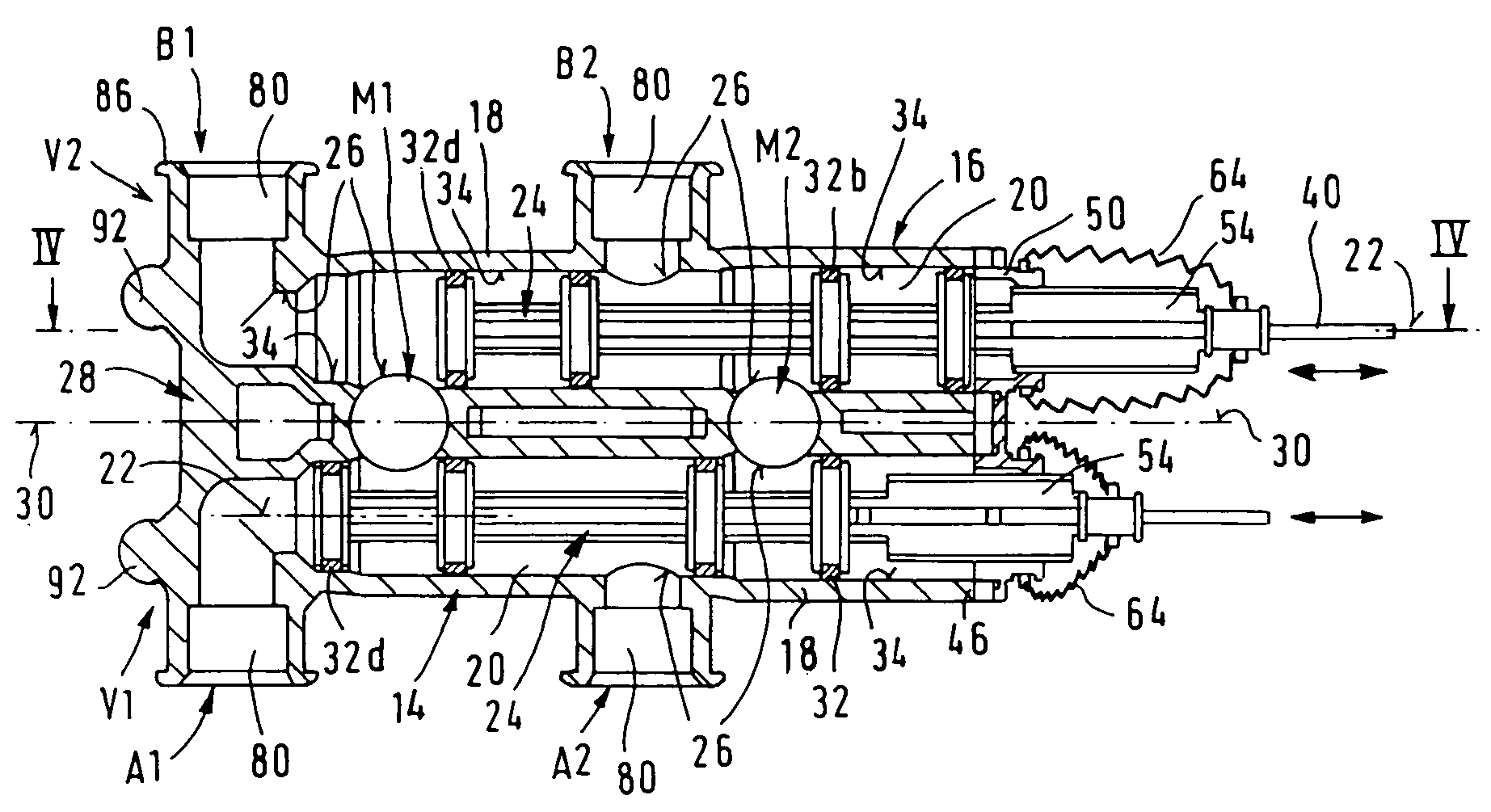
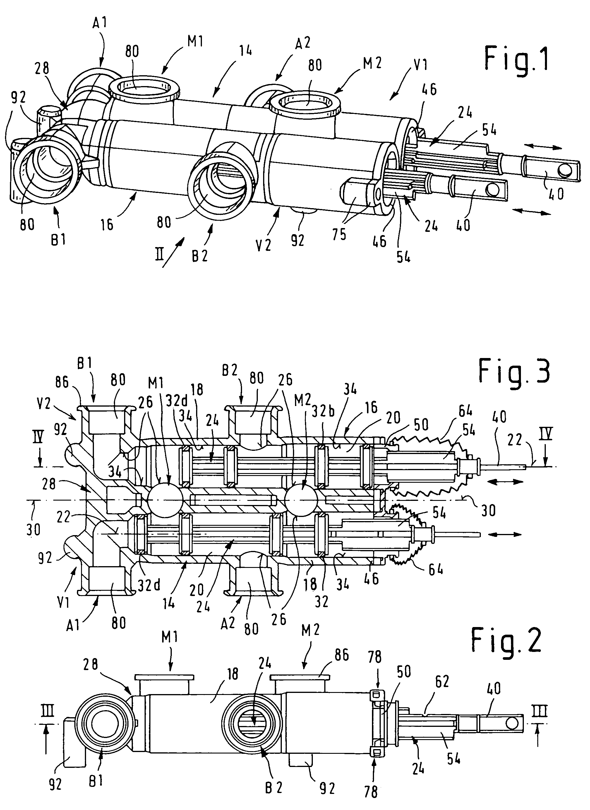
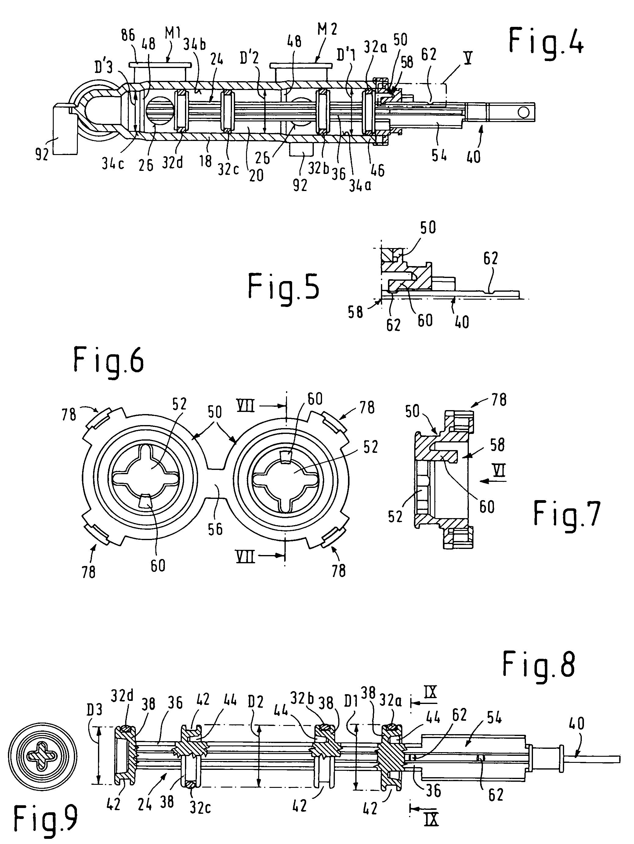
[0038]Identical parts are always given the same reference symbols in the various figures in the drawing.

[0039]As first becomes apparent from FIG. 23, a multiway valve arrangement 1 according to the invention is used, in particular, as a fuel tank changeover valve between two fuel tanks A and B and an engine M, only indicated diagrammatically, in a motor vehicle (motor truck). For this purpose, the valve arrangement 1 has tank connections A1, A2 for the tank A and tank connections B1, B2 for the tank B, the connections A1 and B1 functioning as forward flow tank connections in each case for a tank suction line 2, 4 leading respectively from the tank A and B to the valve arrangement 1, and the connections A2 and B2 functioning as return flow tank connections in each case for a return line 6 and 8 leading back respectively in the direction of the tank A and B. Furthermore, the valve arrangement 1 has two engine connections M1 and M2, the connection M1 being provided as a forward flow en...


PUM


Abstract

The valve device consists, according to the invention, of (at least) two part valves which are symmetrical in circuit terms with respect to the existing connections and which are designed, in particular, as four-way, two position valves of any desired type of construction, but preferably are provided as slide valves. There is preferably a double slide valve with two cooperating slide valves. The valve device features internal seals and sealing surfaces which minimize wear and damage to the seals as they move across flow ports. The valve device is particularly adapted for use as a fuel control valve for an internal combustion powered motor vehicle having two separate fuel tanks. The valve device permits control over which tank supplies fuel to the engine, and allows controlled mixing of the fuels from each tank.

Description

CROSS REFERENCE TO RELATED APPLICATION[0001]This application claims priority to U.S. provisional patent application Ser. No. 60 / 655,200, filed Feb. 22, 2005.FIELD OF THE INVENTION[0002]The present invention relates to a multiway valve arrangement for use as a fuel tank changeover valve between two fuel tanks of a motor vehicle, with two connections for each tank having forward flow and return flow lines. The valve device of this invention enables the forward flow tank connections to be connected alternatively or jointly to the engine and the return flow tank connections can be connected alternatively or jointly to the return flow engine connections.BACKGROUND OF THE INVENTION[0003]In certain regions of the earth, for example in the U.S.A., long distances between zones with high average temperatures and zones with very low temperatures are covered by heavy duty motor trucks in intercity transport. Since heavy duty motor trucks are usually operated with diesel fuel, there is a problem...

Claims


Application Information

Patent Timeline
Patent Type & Authority Patents(United States)
IPC IPC(8): F16K11/00F02B15/00F02M37/00
CPCF02M37/0023F02M37/0088F16K11/20F02D19/0649F02D19/0676Y02T10/36Y02T10/30Y10T137/4673Y10T137/87161Y10T137/87249Y10T137/87281
Inventor HAGEN, HARALDHASBERG, MARKUSSUHR, ANDREAS
Owner VOSS AUTOMOTIVE
Why Eureka
Try Eureka