Switching class A-B amplifier

a technology of switching class and amplifier, applied in the field of electrical amplifier, can solve the problems of mosfets, bipolar counterparts are more expensive, and the amplifier class enjoys no balancing mechanism

Active Publication Date: 2008-05-06
CHARTOLEAUX
View PDF6 Cites 8 Cited by
  • Summary
  • Abstract
  • Description
  • Claims
  • Application Information

AI Technical Summary

Problems solved by technology

Being reliant on such devices, however, this class of amplifier enjoys no balancing mechanism.
MOSFETs, however, are more expensive than their bipolar counterparts, which conduct current only in a single direction.

Method used


Image

  • Switching class A-B amplifier
  • Switching class A-B amplifier

Examples


Embodiment Construction

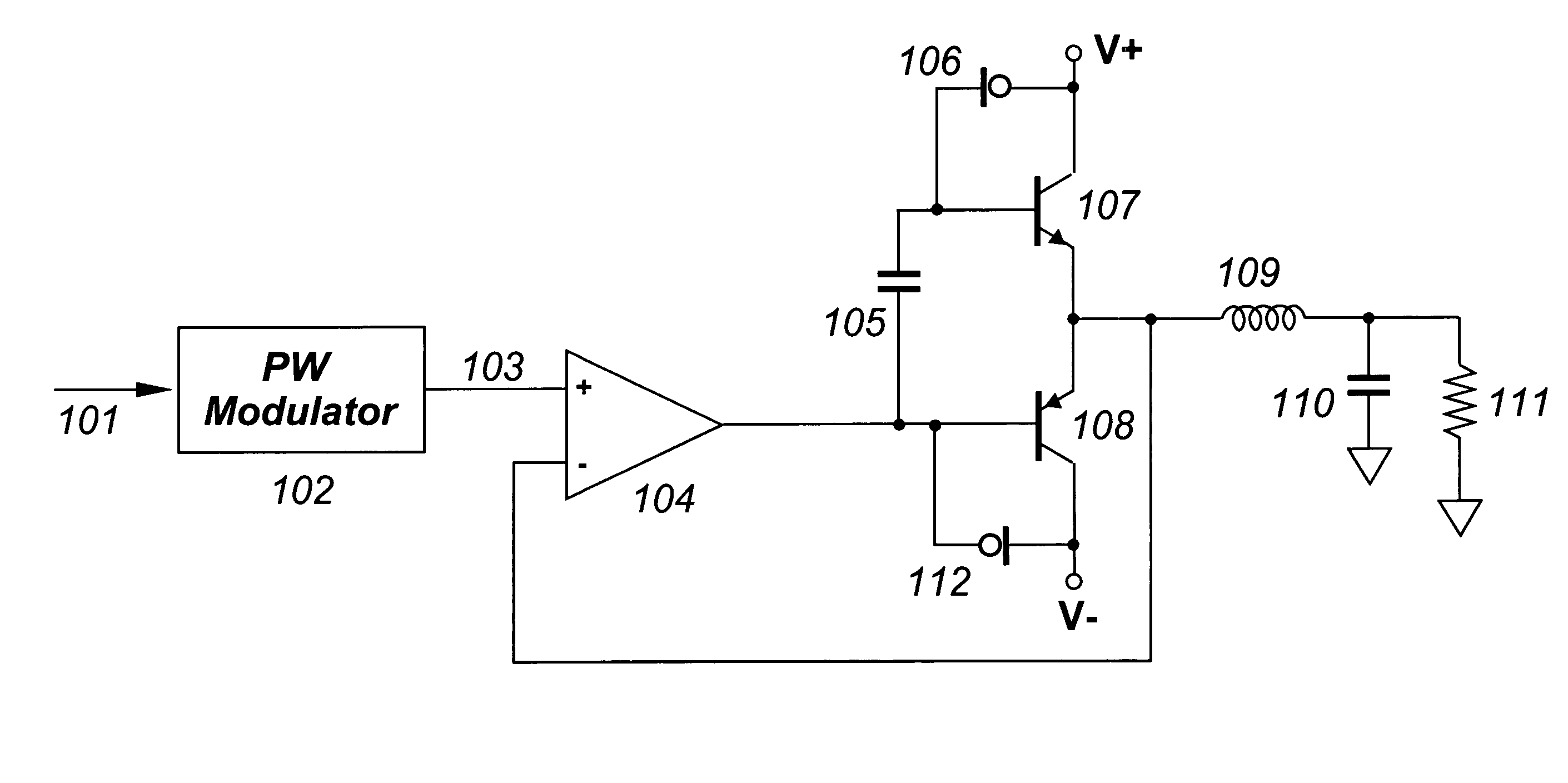
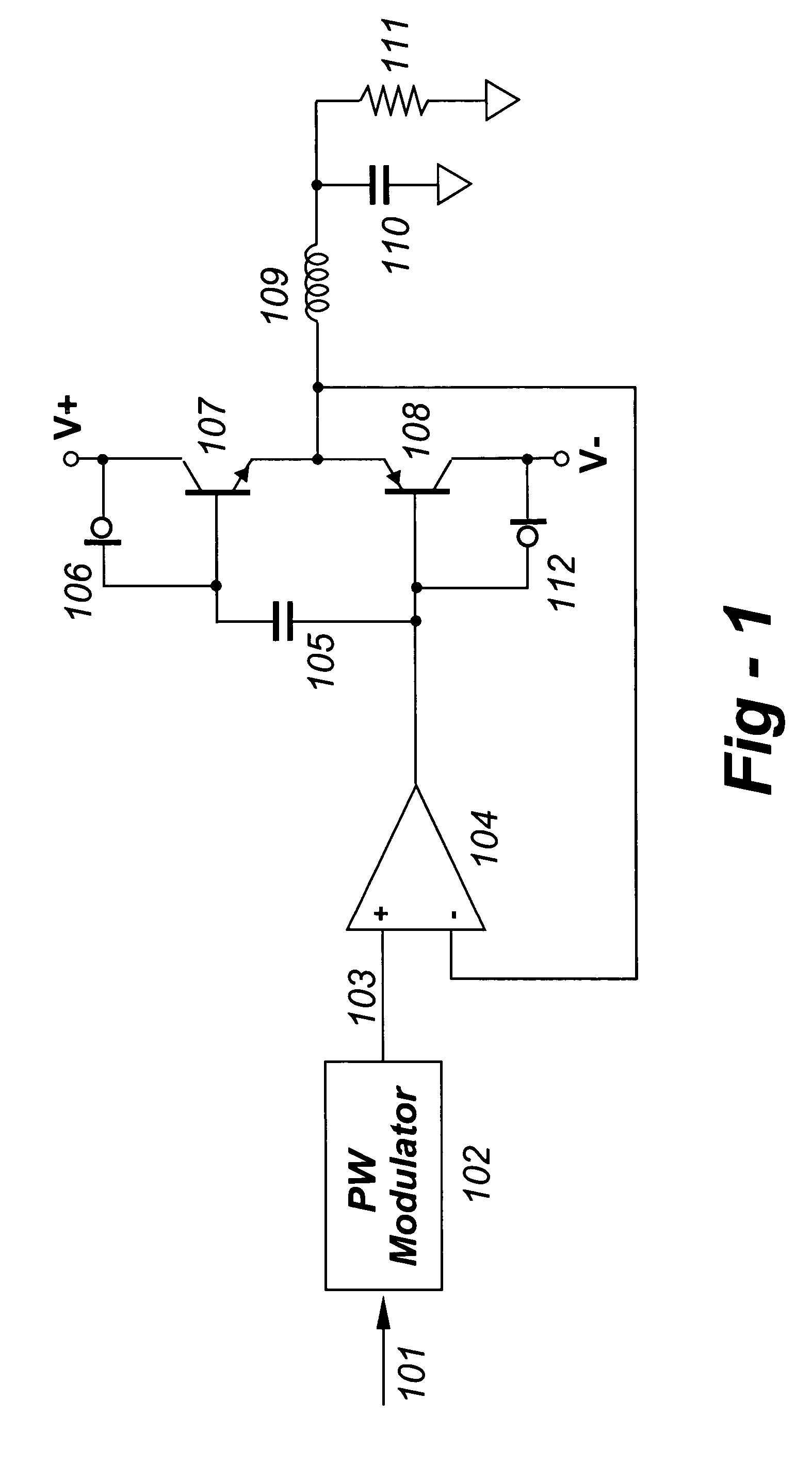
[0009]Referring now to FIG. 1, pulsewidth modulator 102 receives incoming data stream 101 as input, and produces digital pulsewidth stream 103 as output. Pulsewidth stream 103 is constrained to two invariant output levels, as is known in the art.

[0010]Error amplifier 104 receives pulsewidth stream 103 as a non-inverting input, and outputs a voltage to transistor 108 at its base input. The output of error amplifier 104 is similar in nature to pulsewidth stream 103, alternating between two narrowly-constrained voltage ranges.

[0011]Constant current source 106 provides a controlled current through transistor 107, while constant current source 112 provides a controlled current through transistor 108. The net effect is that a constant current flows through both transistors 107 and 108 at all times, in addition to any load current in either device.

[0012]Capacitor 105 couples the AC component of error amplifier 104 output to transistor 107 at its base input, while not disturbing the DC oper...


PUM


Abstract

A circuit configuration and a method enables less-expensive bipolar switching devices to be employed in high-accuracy class D amplifiers. A constant-bias current is provided between the switching devices of a class D amplifier, and, through feedback or appropriate alternative implementation, the output levels of the class D amplifier achieve deterministic voltage levels regardless of current.

Description

REFERENCE TO RELATED APPLICATION[0001]This application claims priority to U.S. Provisional Patent Application Ser. No. 60 / 565,746, filed Apr. 27, 2004, the entire content of which is incorporated herein by reference.FIELD OF THE INVENTION [0002]This invention relates generally to electronic amplifiers and, in particular, to a circuit configuration and a method whereby less-expensive bipolar switching devices may be employed in high-accuracy class D amplifiers.BACKGROUND OF THE INVENTION[0003]Class A-B amplifiers ensure accurate amplification through the balance of non-saturated sink and source (push-pull) output stage sections which each provide current of a single polarity through both polarities of the output.[0004]Class D amplifiers yield higher efficiency than class A-B amplifiers, through use of saturated mutually-exclusive sink and source switching devices. Being reliant on such devices, however, this class of amplifier enjoys no balancing mechanism. In that current in the out...

Claims


Application Information

Patent Timeline
Patent Type & Authority Patents(United States)
IPC IPC(8): H03F3/38H03F3/217
CPCH03F3/217H03F3/38
Inventor KIRN, LARRY
Owner CHARTOLEAUX
Why Eureka
Try Eureka