
Circuit configuration having a feedback operational amplifier

a circuit configuration and operational amplifier technology, applied in amplifiers, amplifiers with semiconductor devices/discharge tubes, electrical instruments, etc., can solve the problems of reducing the linearity of the circuit configuration, limiting the linearity of the resistor, and not satisfying both objects in all applications, so as to achieve the effect of affecting the output signal

Active Publication Date: 2008-05-06
NAT SEMICON GERMANY
View PDF4 Cites 11 Cited by
  • Summary
  • Abstract
  • Description
  • Claims
  • Application Information

AI Technical Summary

Benefits of technology

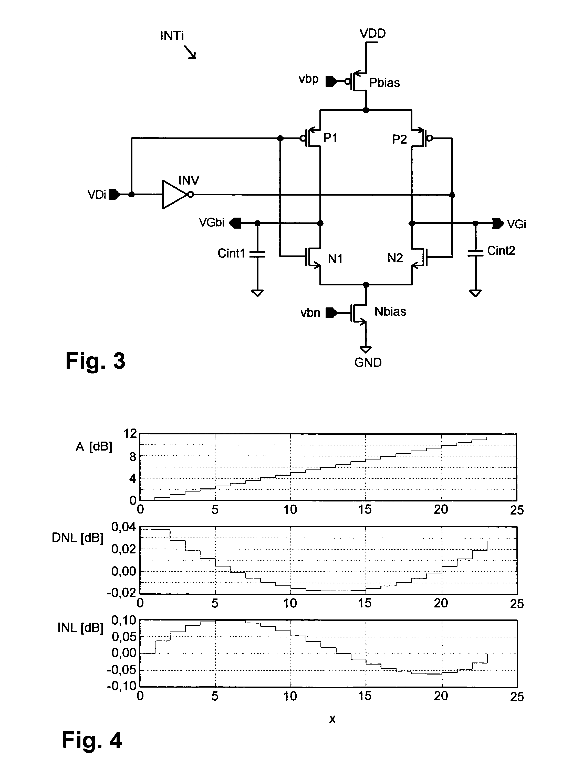
This approach enables easy and reliable adjustment of circuit amplification with improved linearity and reduced noise, allowing for a range of amplification from 0 dB to 12 dB with minimal quantization error, effectively addressing the limitations of previous technologies.

Problems solved by technology

Both achievements of the object are not satisfactory in all applications.
In the second achievement of the object, above all, a disadvantage is the restricted linearity of the resistors implemented by MOS transistors in the triode range and, accompanying this, a reduced linearity of the circuit configuration.
In addition, a further disadvantage of the known circuit configurations is that their output signal is often impaired by interference signals, particularly noise unavoidably occurring at the input side of the operational amplifier, for example.
A greater resistance value results in a greater effective noise voltage.
Although resistance values this low may be implemented in CMOS technology, it is extremely difficult to change resistance values of this type in operation at great precision or with high linearity in relation to an activation signal in order to change the circuit amplification precisely during operation of the circuit configuration.

Method used


Image

  • Circuit configuration having a feedback operational amplifier
  • Circuit configuration having a feedback operational amplifier
  • Circuit configuration having a feedback operational amplifier

Examples


Embodiment Construction

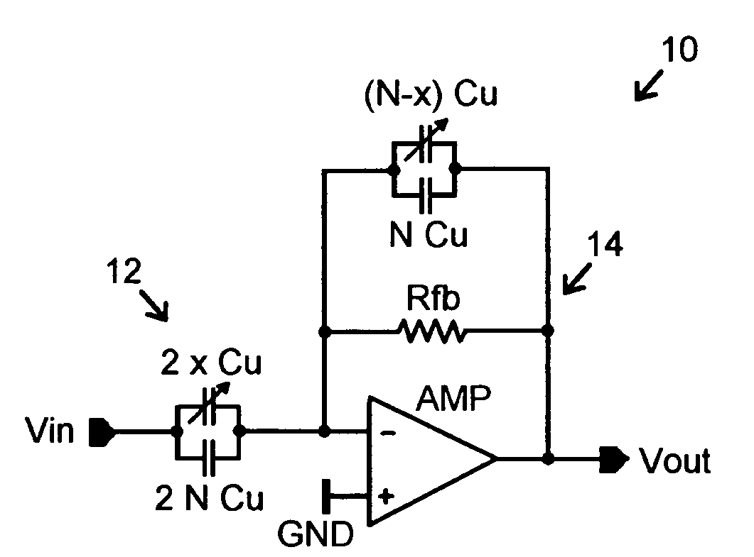
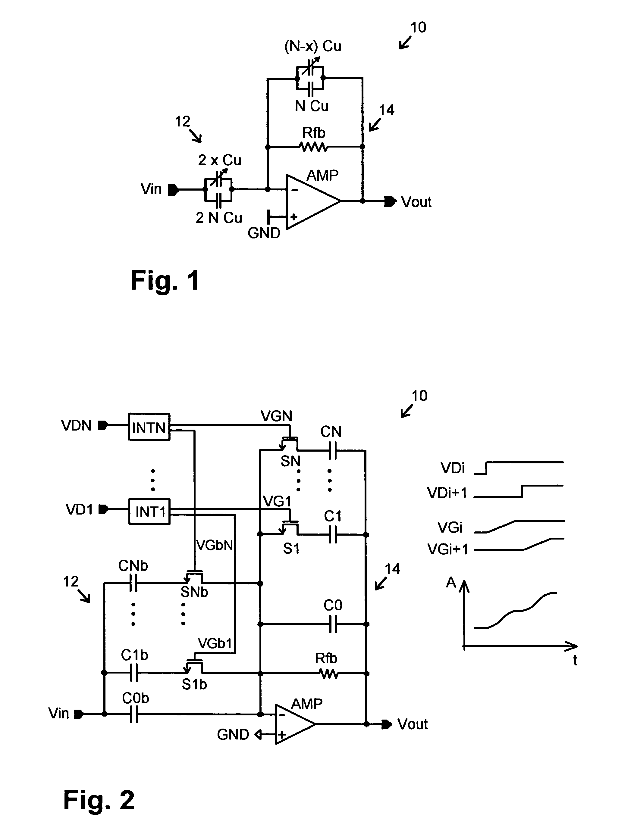
[0052]On the left, FIG. 1 shows a circuit configuration identified overall by 10 having a circuit input for an input signal Vin to be amplified and a circuit output to output the amplified input signal as an output signal Vout.

[0053]The circuit configuration 10 comprises an operational amplifier AMP, whose amplifier input is impinged in the way shown with the input signal Vin and at whose amplifier output the amplified input signal is provided, the operational amplifier being fed back using a feedback network to define the circuit amplification (=Vout / Vin).

[0054]The feedback network comprises a coupling path 12 running from a circuit input terminal to an inverting amplifier input terminal and a feedback path 14 running from an amplifier output terminal to the inverting amplifier input terminal.

[0055]The coupling path 12 and the feedback path 14 each comprise a parallel circuit made of capacitive coupling branches.

[0056]A first coupling branch, which is below in each case in FIG. 1, ...


PUM


Abstract

The present invention relates to a circuit configuration (10) having a feedback operational amplifier (AMP) for amplifying an input signal (Vin) input into the circuit arrangement (10) and outputting the amplified input signal as an output signal (Vout). In order to be able to change the circuit amplification (Vout / Vin) easily and reliably in the circuit configuration (10) and simultaneously keep an impairment of the output signal (Vout) caused by noise relatively low, capacitance values (Cb, C) of the coupling path (12) and of the feedback path (14) are adjusted simultaneously to one another correlated in a special way.

Description

BACKGROUND OF THE INVENTION[0001]1. Area of the Invention[0002]The present invention relates to a circuit configuration having a feedback operational amplifier for amplifying an input signal input into the circuit configuration and outputting the amplified input signal as an output signal.[0003]Circuit configurations of this type are known in manifold forms. Solely for exemplary purposes, reference is made to the textbooks “U. Tietze, Ch. Schenk, Halbleiter-Schaltungstechnik [Semiconductor Circuit Technology], 5th Edition, Springer-Verlag, 1980”, in particular pages 93 through 108, and “Paul Horwitz, Winfield Hill, The Art of Electronics, Second Edition, Cambridge University Press, 1989”, in particular pages 175 through 195.[0004]The term “operational amplifier” as defined in the present invention is to be understood very broadly as a configuration capable of amplifying an electrical variable such as a voltage. In particular, it refers to amplifiers, for example, in which a signal a...

Claims


Application Information

Patent Timeline
Patent Type & Authority Patents(United States)
IPC IPC(8): H03F1/36
CPCH03F3/45183H03F3/45475H03F2203/45526H03F2203/45534H03F2203/45548
Inventor BLON, THOMAS
Owner NAT SEMICON GERMANY
Learn More