Dispersion compensation method and apparatus

Inactive Publication Date: 2008-05-06
LUCENT TECH INC
View PDF12 Cites 7 Cited by
  • Summary
  • Abstract
  • Description
  • Claims
  • Application Information

AI Technical Summary

Benefits of technology

[0009]In accordance with one embodiment of the present invention, periodic-group-delay dispersion compensation modules (PGD-DCM's) are used to provide a portion of the dispersion-compensation in a dispersion managed span, which results in drastic reduction of the collision-induced timing jitter in dense WDM-DMS systems.
[0010]In another embodiment of the invention a dispersion compensator is provided for use in a dense wavelength division multiplexed optical communication system. The compensator comprises a periodic-g

Problems solved by technology

Dense WDM-DMS systems, however, tend to suffer one significant nonlinear penalty, i.e., a jitter in pulse arrival times resulting from the collisions between solitons of different channels.
It is these large per-collision time shifts, compounded by the poor statistics of just a handful of collisions, that tend to create eye-closing timing jitter for distances in excess of about 5000 km.
The different nature of the penalties also results in the fact that wh

Method used


Image

  • Dispersion compensation method and apparatus
  • Dispersion compensation method and apparatus
  • Dispersion compensation method and apparatus

Examples


Embodiment Construction

[0021]Unless otherwise noted, or as may be evident from the context of their usage, any terms, abbreviations, acronyms or scientific symbols and notations used herein are to be given their ordinary meaning in the technical discipline to which the invention most nearly pertains. The following terms, abbreviations and acronyms are used in the description contained herein:

[0022]

ASKamplitude shift keyingDCFdispersion compensating fiberDCMdispersion compensation moduleDMSdispersion-managed solitonDPSKdifferential phase-shift keyingDQPSKdifferential quadrature phase-shift keyingEDFAErbium-doped fiber amplifierNRZnon-return-to-zeroNZDSFnon-zero dispersion-shifted fiberOOKon-off keyingPGDperiodic-group-delayRZreturn-to-zeroSPMself phase modulationULHultra-long haulWDMwavelength division multiplexing (or multiplexed)WGRwaveguide grating routerXPMcross phase modulation

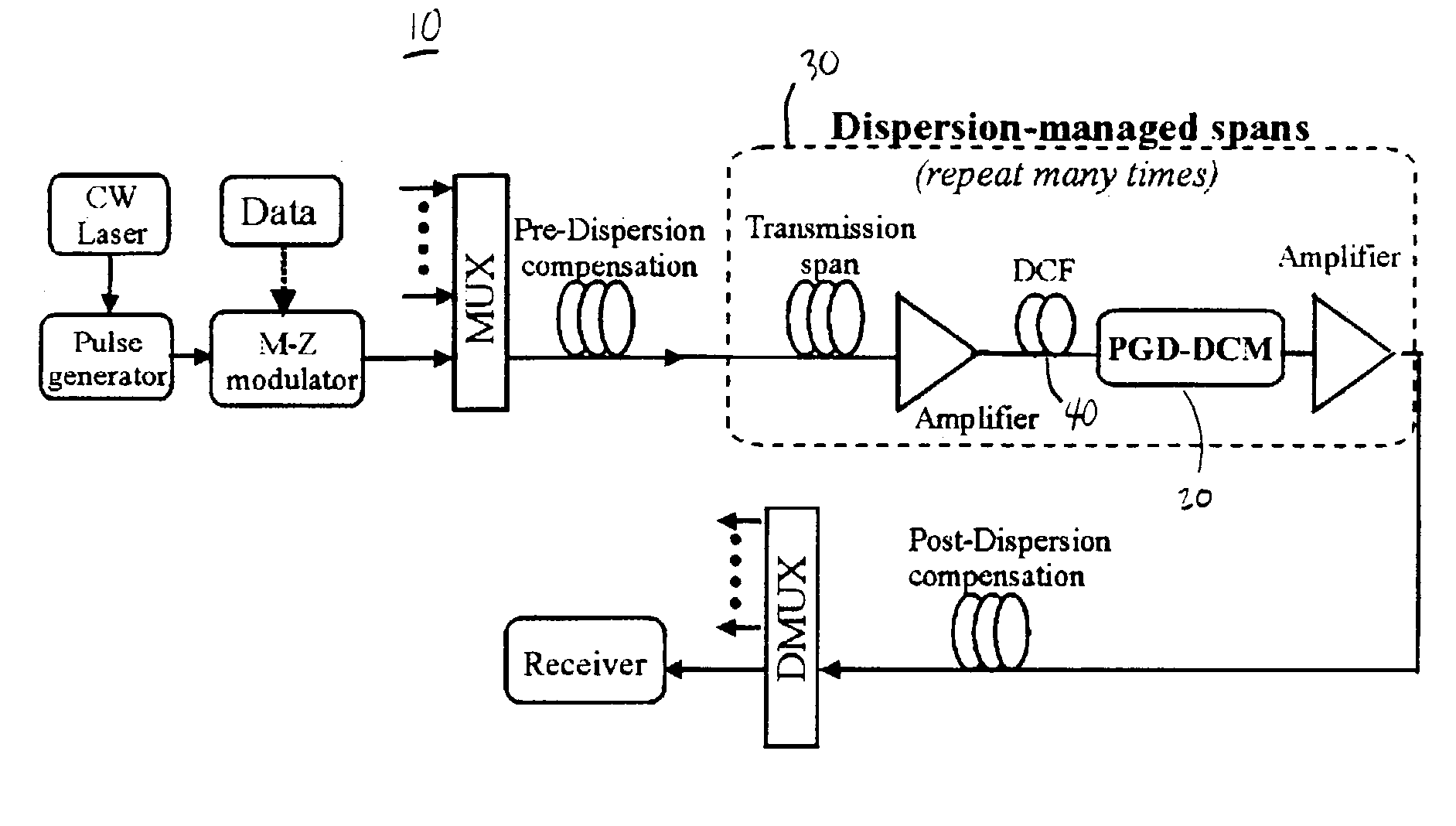
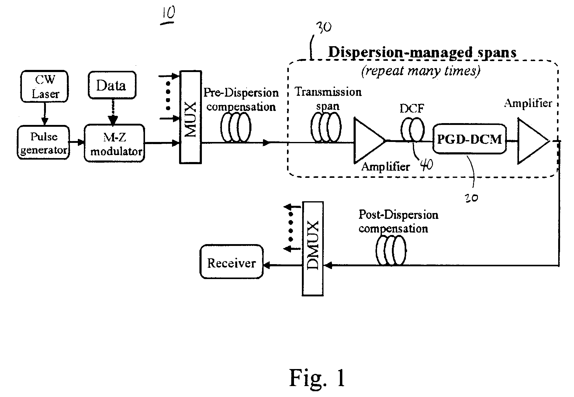
[0023]A schematic diagram of a system 10 in accordance with one embodiment of the present invention is shown in FIG. 1. One or...


PUM


Abstract

In one embodiment of the invention a dispersion compensator is provided for use in a dense wavelength division multiplexed optical communication system. The dispersion compensator comprises a periodic-group-delay dispersion compensation module which provides a portion of the dispersion compensation for a dispersion managed span of the optical communication system. A remaining portion of the dispersion compensation for the dispersion managed span is provided by dispersion compensating fiber. The portions of the dispersion compensation provided by each of the periodic-group-delay dispersion compensation module and the dispersion compensating fiber is selected such that the collision-induced timing jitter is reduced.

Description

TECHNICAL FIELD[0001]The present invention relates to optical communications, and more particularly to dispersion compensation for high bit rate ultra-long haul (ULH) wavelength division multiplexed (WDM) optical communication systems using dispersion-managed solitons (DMS) or other transmission formats.BACKGROUND OF THE INVENTION[0002]DMS is a proven technology to extend the ultimate reach of high bit rate (e.g. 10 Gb / s) optical fiber communication systems by balancing the optical fiber's dispersion and nonlinearity. Dense WDM-DMS systems, however, tend to suffer one significant nonlinear penalty, i.e., a jitter in pulse arrival times resulting from the collisions between solitons of different channels.[0003]When the dispersion compensation of a transmission span is accomplished with only dispersion-compensating fiber DCF, a pair of colliding pulses (from different channels) dart back and forth with respect to each other in retarded time, in a sawtooth motion typically several hund...

Claims


Application Information

Patent Timeline
IPC IPC(8): H04B10/12H04B10/00H04B10/18H04J14/02
CPCH04B10/25253H04J14/02
Inventor LIU, XIANGMOLLENAUER, LINN FREDERICKWEI, XING
Owner LUCENT TECH INC
Why Eureka
Try Eureka