Method of full light control laser synchronization

A technology of lasers and lasers, which is applied in the direction of lasers, laser components, optics, etc., can solve the problems of unrealizable and long-distance light control, and achieve the effect of small time jitter

Inactive Publication Date: 2008-06-04
EAST CHINA NORMAL UNIV
View PDF4 Cites 0 Cited by
  • Summary
  • Abstract
  • Description
  • Claims
  • Application Information

AI Technical Summary

Problems solved by technology

Optical control synchronization can obtain lower time jitter and make up for the lack of circuit synchronization. However, the existing optical control synchronization scheme has certain limitations, that is, the Kerr medium is located in the cavity of the laser cavity, so long-distance optical control cannot be realized. That is, it cannot be realized when the two lasers are far apart

Method used


Image

  • Method of full light control laser synchronization
  • Method of full light control laser synchronization
  • Method of full light control laser synchronization

Examples


Embodiment 1

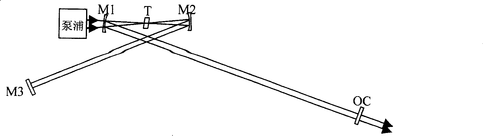
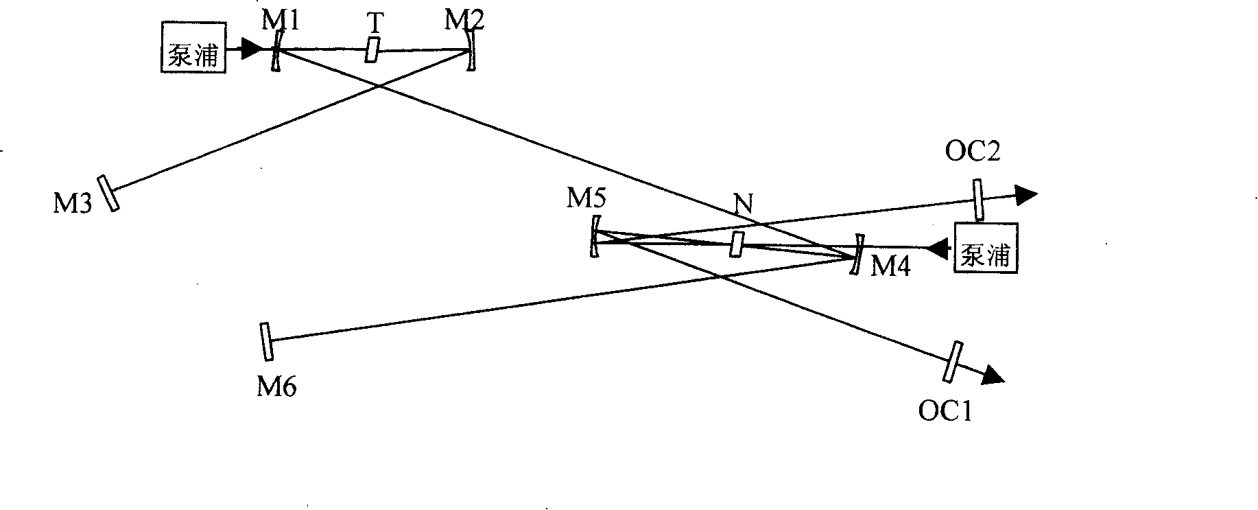
[0028] Embodiment 1: as Figure 4 As shown, this embodiment is a form of expression constituting the above-mentioned structural units. Insert a confocal cavity composed of M4 and M5 into the laser composed of cavity mirrors labeled M1, M2, M3 and OC, place the Kerr medium N at the focus of the confocal cavity, and T is the gain of the laser As the medium, titanium-doped sapphire (Ti:S) is selected in this embodiment. Among them, M1, M2, M4, and M5 are concave mirrors, M3 is a plane mirror, and OC is an output coupling mirror. The cavity mirror is coated with different dielectric coatings for different wavelength bands. M6 and M7 are concave reflectors with the same curvature as M4 and M5, and their function is to focus the laser output from laser 1 onto the Kerr medium. N is the Kerr medium. In this embodiment, titanium-doped sapphire is used and placed in M6, The common focal point of the confocal cavity formed by M7 and the confocal cavity formed by M4 and M5. When the i...

Embodiment 2

[0029] Embodiment 2: as Figure 5 As shown, this embodiment constitutes another form of expression of the above-mentioned structural unit, and its difference from Embodiment 1 is that it does not directly focus the distant laser light into the Kerr medium, but couples it into a In the passive enhancement cavity composed of M6, M7 and plane mirrors M8, M9 (passive cavity for short), the focus of the passive cavity and another laser composed of M1, M2, M3, M4, M5 and OC are in the Kerr medium The focus on . In this way, the light intensity on the Kerr medium can be greatly increased, and the cross-phase modulation effect can be enhanced, which is more conducive to realizing the synchronization of the two beams. The more complicated part of this embodiment is that to couple the distant laser into the passive cavity, it must be ensured that the passive cavity and the distant laser oscillation cavity have exactly the same free spectral region. Therefore, it is necessary to lock t...

Embodiment 3

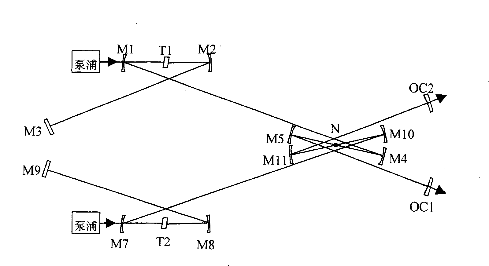
[0030] Embodiment 3: as Image 6 As shown, the difference between this embodiment and embodiment 1 is that a series-connected all-optical control synchronization system composed of two structures shown in embodiment 2 is adopted, that is, the series connection of two structural units, the principle is the same as that of embodiment 2, and can realize 3-color full optical control synchronization, where M1 and M2 are plane reflectors.


PUM


Abstract

This invention relates to a method for realizing total optical control laser synchronization in far distance, which utilizes the cross phase modulation action of multiple lasers in medium to realize synchronous control of far distance multi-beam laser. Advantage: small dithering of time, far distance multi-color total optical control laser synchronization can be realized, when the absolute phase of a far beam is locked, other beams can trace locking automatically so as to get new beams.

Description

technical field [0001] The invention relates to the field of ultrafast lasers, in particular to a method for long-distance realization of all-optical control laser synchronization. Background technique [0002] In recent years, with the development of laser technology, great progress has been made in the fields of ultrafast science, nonlinear optics, optical frequency measurement, and precision spectroscopy. With the development of ultrafast laser and fine measurement technology of optical frequency, the synchronous locking of two lasers has become a hotspot attracting many scientists because of its application value in the field of beam coherence control. In the research, the synchronization of the two beams has been realized through the circuit, but there are large time jitter and random time delay. Therefore, researchers are committed to using all-optical control to realize the synchronization of beams. The main principle of the realization is to inject two beams of ligh...

Claims


Application Information

Patent Timeline
Patent Type & Authority Patents(China)
IPC IPC(8): H01S3/00G02F1/35
Inventor 韩晓红曾和平
Owner EAST CHINA NORMAL UNIV
Why Eureka
Try Eureka