Apparatus and method for storing and transporting data related to vapor emissions and measurements thereof

a technology of vapor emission and apparatus, applied in the field of apparatus and methods for detecting vapor emission and storing and transporting data related thereto, can solve the problems of significant stress on the wire data cable in the current art at the termination point, data corruption, cable damage, etc., and achieve the effect of improving reliability and data protection

Active Publication Date: 2008-05-06
TMX2
View PDF34 Cites 34 Cited by
  • Summary
  • Abstract
  • Description
  • Claims
  • Application Information

AI Technical Summary

Benefits of technology

[0007]The present invention is directed to a system and method which detects vapor emissions then stores and electronically transports data related thereto. Whereas the current art experiences failures induced by the dynamics of the measurement process and is susceptible to loss of data integrity the present invention improves both reliability and data protection.
[0010]In this embodiment of the present invention eliminates the wire data cable that extends from emissions measuring device at the backpack to the tester's hand held apparatus. In place of a cable, a wireless connection is used to link the emissions measuring device to a compatible wireless data-logger device. Such data-logger device may comprise a Personnel Data Assistant (PDA) or other device with a storage medium, microprocessor and transceiver for wireless communication. The storage medium comprises any medium of sufficient capacity capable of storing binary numbers. The wireless link or connection eliminates the economic loss of the current art approach. Additionally, the emissions measuring device is coupled with an additional storage medium which serves as a redundant storage location for sample data. Such sample data is wirelessly transported to the hand held data-logger device.

Problems solved by technology

In the course of performing tests, the wire data cable in the current art is under significant stress at the its termination points.
Frequently the cable becomes damaged and may corrupt data.
Eventually the cable completely fails and requires repair or replacement.
This precipitates economic loss of test time and cost of material repair or replacement.

Method used


Image

  • Apparatus and method for storing and transporting data related to vapor emissions and measurements thereof
  • Apparatus and method for storing and transporting data related to vapor emissions and measurements thereof
  • Apparatus and method for storing and transporting data related to vapor emissions and measurements thereof

Examples


Embodiment Construction

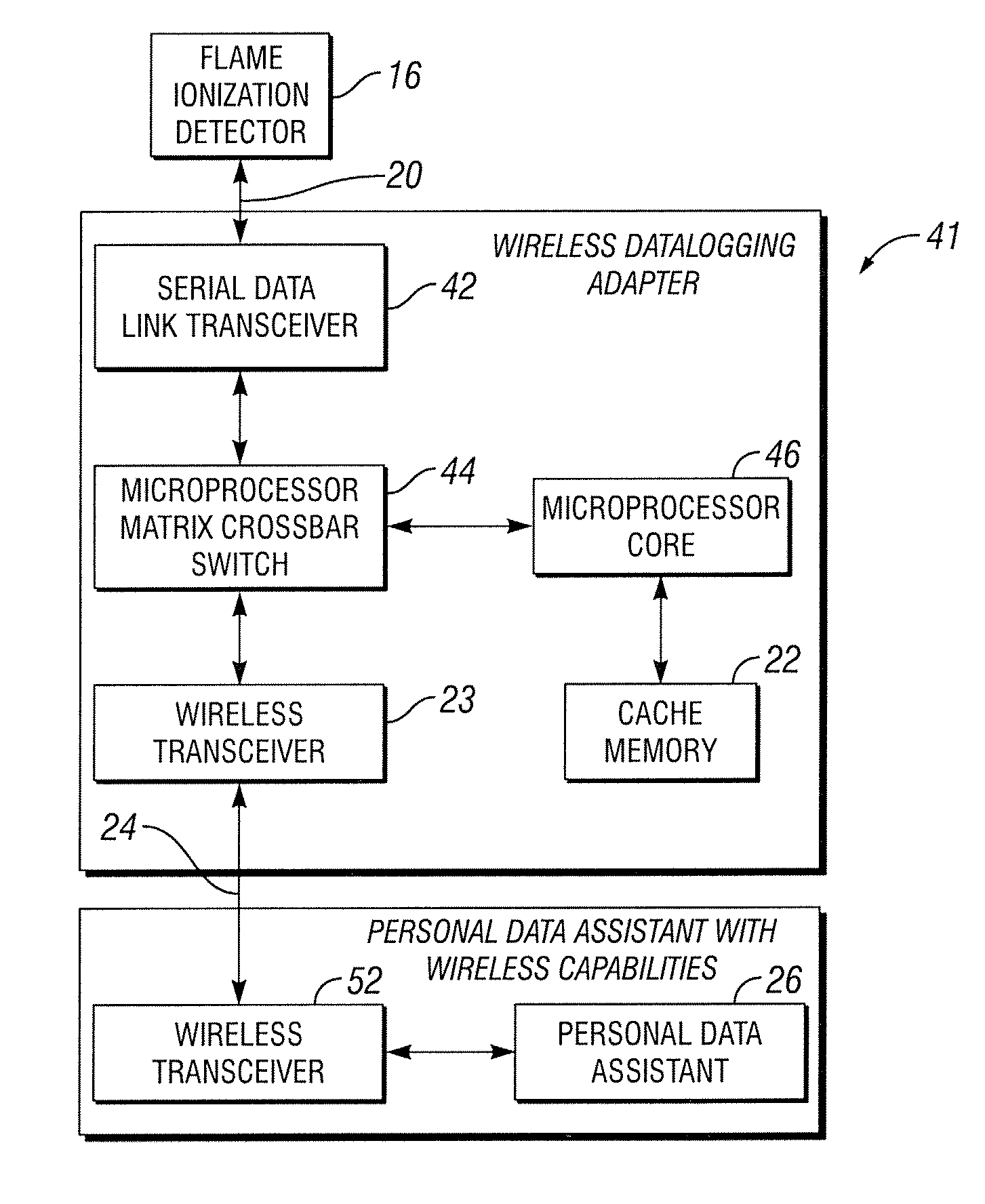
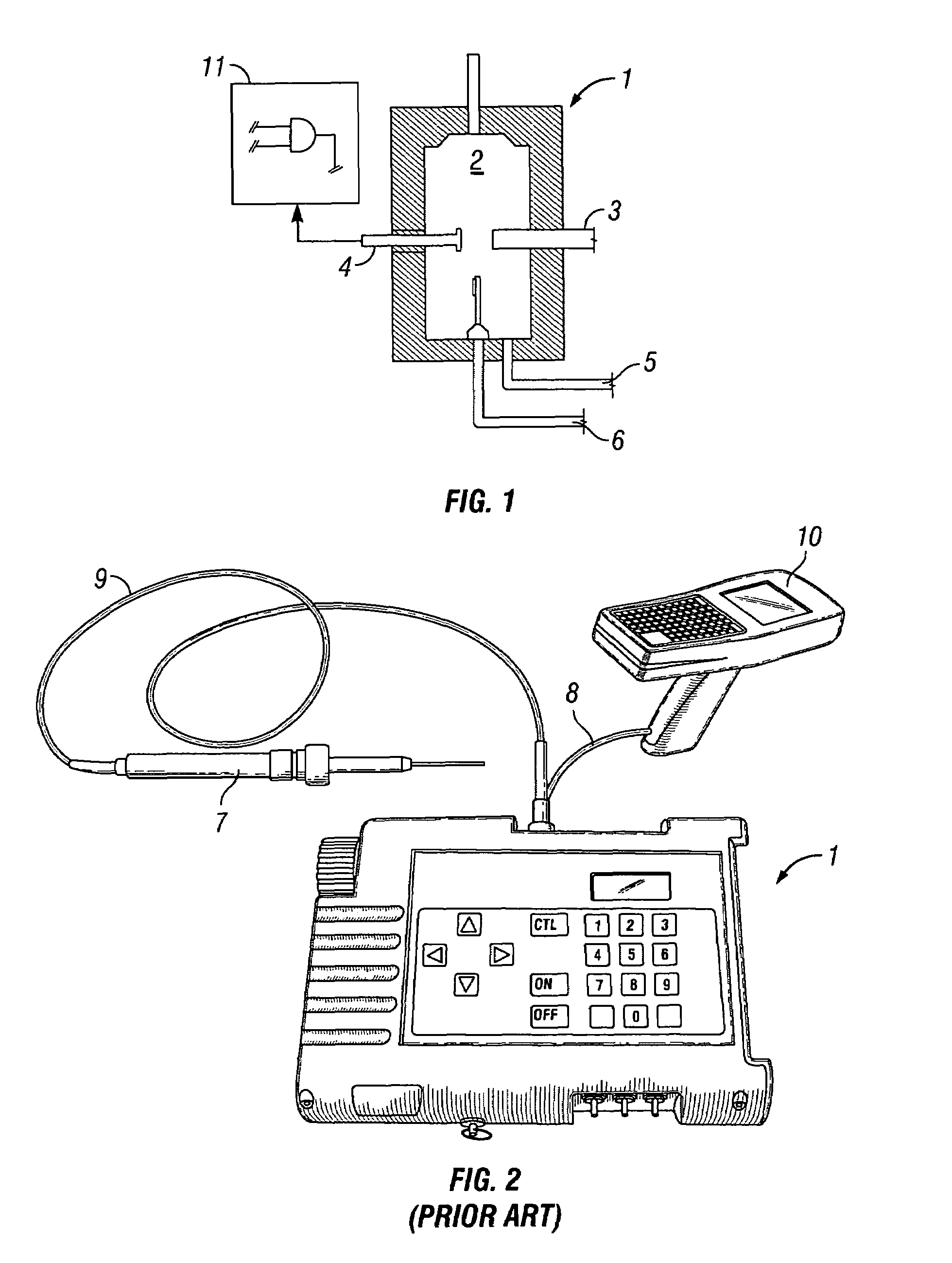
[0025]FIG. 1 shows the mechanical view of basic components of a typical flame ionization detector 1 used to detect vapor, gas and other fugitive emissions from pipes and pipe connections. The cavity 2 is where the fugitive gas sample 5 is drawn internally along with Hydrogen gas 6. On command from, for example, a wireless data-logger adapter, an ignition filament 3 ignites the gas mixture. A collector electrode 4 measures an ionization level that is translated into level of fugitive vapor or gas. Fugitive vapor data is digitized in the flame ionization detector electronic circuit board 11. The digitized fugitive vapor sample data is serialized and provides a serial data transceiver interface to, for example, a wireless data-logger adapter.

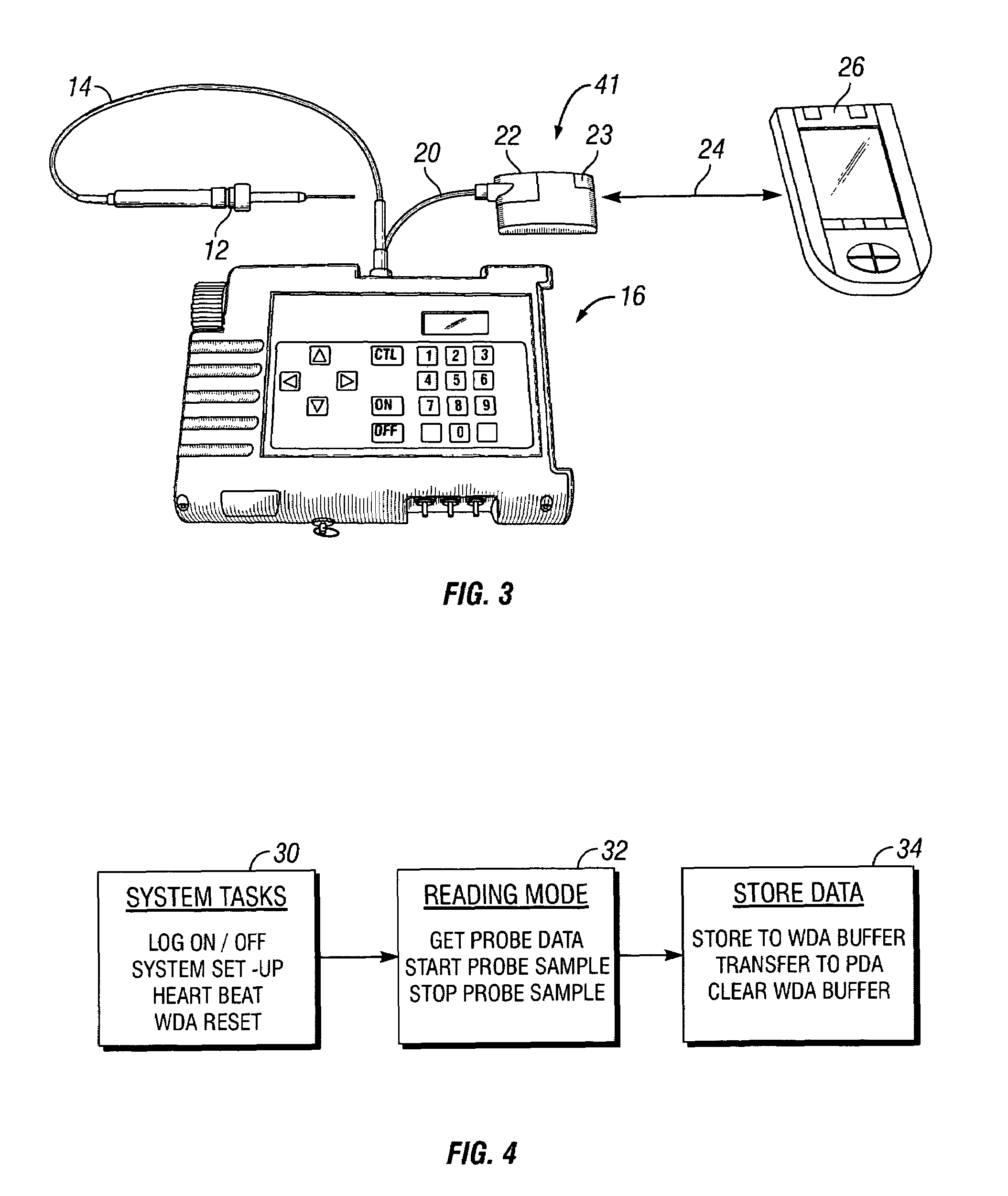
[0026]FIG. 2 is block diagram that shows the current art used to capture Fugitive Emissions from petrochemical and refinery facilities. A gas collection probe 7 takes samples of air in the vicinity of piping sealed joints. Samples drawn into the co...


PUM


Abstract

The present invention provides apparatus and a methods for collecting, transmitting and storing fugitive gas emission data. An embodiment of the invention collects fugitive gas with a sampling probe and into a emission monitoring device. The device then sends and stores fugitive gas data into a storage medium, such as a wireless data-logging adapter. The wireless-data logging adapter stores the data and wirelessly sends it to a personal digital assistant or other form of redundant memory such as a data logger. In one embodiment, the PDA can initiate commands to retrieve data from the storage medium or operate the emission gas monitoring device.

Description

CROSS-REFERENCE TO RELATED APPLICATIONS[0001]This application claims the benefit of U.S. Provisional Patent Application, Ser. No. 60 / 616,308, filed Oct. 5, 2004, now expired, the contents of which is incorporated herein by reference.TECHNICAL FIELD[0002]The present invention relates generally to the petrochemical and refinery field and more particularly to an apparatus and method for detecting vapor emissions and storing and transporting data related thereto.BACKGROUND OF THE INVENTION[0003]Petrochemical and refinery facilities move volatile fluids between processes through a complex array of pipes. Pipes are joined in tandem have sealed joints to prevent fugitive emissions. Pipes not joined in tandem have sealed end caps to avoid fugitive emissions. Conditions may be such that leaks develop at the seal points. These leaks, or fugitive emissions, are toxic and explosive and represent a threat to human life and property.[0004]In order to avoid the dire results of pipe seal failures, ...

Claims


Application Information

Patent Timeline
Patent Type & Authority Patents(United States)
IPC IPC(8): G06F17/40G06F19/00
CPCG01N27/626G01N35/00871G01N2001/2285
Inventor MILLER, TERRYCARNES, HOWARD
Owner TMX2
Why Eureka
Try Eureka