Vapor compression refrigerating systems

a refrigerating system and vapor compression technology, applied in refrigeration components, mechanical equipment, light and heating equipment, etc., can solve the problems of increasing the thermal resistance of the compressor, the need to increase the power required for compressor operation, and the discharge temperature of the compressor may be elevated to an undesirable level, so as to reduce the degree of superheating and increase the coefficient of performance of the refrigerating system

Inactive Publication Date: 2008-05-13
SANDEN CORP
View PDF1 Cites 9 Cited by
  • Summary
  • Abstract
  • Description
  • Claims
  • Application Information

AI Technical Summary

Benefits of technology

[0009]Accordingly, it is an object of the present invention to provide vapor compression refrigerating systems, in particular, vapor compression refrigerating systems using carbon dioxide refrigerant, which may reduce the degree of superheating of the refrigerant at a suction side of a compressor, and which may increase a coefficient of performance of the refrigerating system.
[0015]Further, a vapor compression refrigerating system, according to the present invention, may operate at a supercritical condition and comprises a compressor for compressing refrigerant, a radiator for reducing the temperature of refrigerant with an elevated temperature and an elevated pressure compressed by the compressor, a first pressure-reducing means for reducing a pressure of refrigerant having been passed through the radiator, a second pressure-reducing means for further reducing a pressure of refrigerant (m) reduced in pressure by the first pressure-reducing means, and a refrigerant branching means for dividing the pressure reduced refrigerant. The temperature of refrigerant compressed by the compressor is reduced by the radiator, the refrigerant passed through the radiator is reduced in pressure by the first pressure-reducing means, the pressure reduced refrigerant (m) is reduced further in pressure by the second pressure-reducing means, and the pressure reduced refrigerant (m′) is divided by the refrigerant branching means into a plurality of portions, one portion refrigerant (m1) exchanges heat with the refrigerant (m) reduced in pressure by the first pressure-reducing means by a cooler, thereby reducing the temperature of the pressure reduced refrigerant (m). An other portion of refrigerant (m2) is evaporated by an evaporator, the evaporated refrigerant (m2′) and the refrigerant (m1′) having passed through the cooler are mixed by a gas / liquid separator (e.g, an accumulator) provided for separating gas / liquid of refrigerant, and the mixed refrigerant is introduced into the compressor (i.e., a second vapor compression refrigerating system).
[0017]Further, a structure also may be employed wherein the first pressure-reducing means is configured to adjust a degree of pressure reduction, and the degree of pressure reduction is adjusted by a pressure or a temperature, or both, of refrigerant flowing into the first pressure-reducing means. Further, a structure may be employed wherein an outside air temperature detecting means for detecting a physical value having a correlation with an outside air temperature is provided, and when the physical value having a correlation with an outside air temperature detected by the outside air temperature detecting means is equal to or less than a predetermined value, the refrigerant branching means prevents the flow of refrigerant into the cooler. In another embodiment, a structure may be employed wherein a higher pressure detecting means for detecting a physical value having a correlation with a refrigerant pressure at a higher-pressure side in said refrigerating cycle from the compressor to the first pressure-reducing means is provided, and when the physical value having a correlation with a refrigerant pressure at the higher-pressure side detected by the higher pressure detecting means is equal to or less than a predetermined value, the refrigerant branching means prevents the flow of refrigerant into the cooler.
[0019]Thus, in the vapor compression refrigerating system according to the present invention, and particularly as a vapor compression refrigerating system using carbon dioxide refrigerant which is a natural-system refrigerant, the dryness of the refrigerant of the refrigerating system at an entrance of the evaporator may be reduced, and the refrigerating capacity of the evaporator may be increased. Further, the superheating degree of refrigerant at the suction side of the compressor may be reduced as compared with that in the known refrigerating system using an internal heat exchanger for exchanging heat between the suction side of the compressor and the exit side of the radiator. Because the efficiency of the compressor may be improved and the discharge temperature thereof may be lowered, the coefficient of performance of the refrigerating system may be increased.

Problems solved by technology

As a result, the discharge temperature of the compressor also may be elevated to an undesirable level.
Therefore, in the above-described refrigerant system, the need to increase the thermal resistance of the compressor and the increased power required for compressor operation may be undesirable.

Method used


Image

  • Vapor compression refrigerating systems
  • Vapor compression refrigerating systems
  • Vapor compression refrigerating systems

Examples


Embodiment Construction

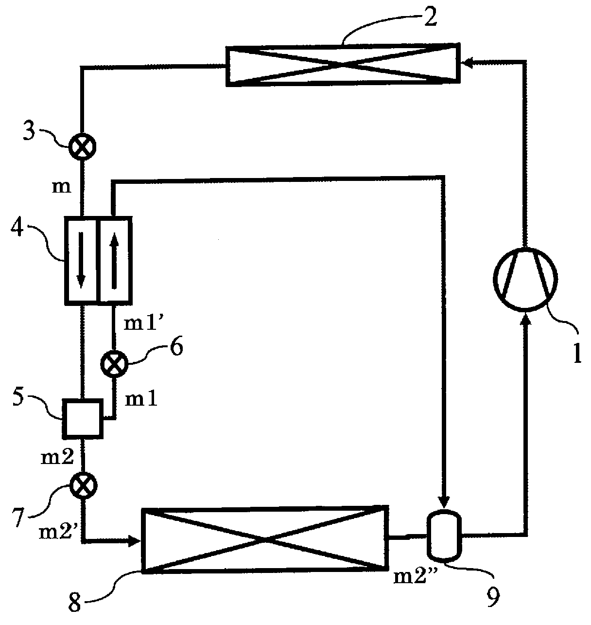
[0032]FIG. 1 depicts a main structural part of a vapor compression refrigerating system according to an embodiment of the present invention, using carbon dioxide refrigerant which is natural-system refrigerant. In this refrigerating system, refrigerant compressed by a compressor 1 is introduced into a radiator 2, the refrigerant exchanges heat with an external fluid. The refrigerant passed through radiator 2 is reduced in pressure by a first pressure reducing mechanism 3 provided as a first pressure-reducing means at the exit side of radiator 2. The pressure reduced refrigerant (m) is divided into a plurality of portions by a refrigerant branching mechanism 5 provided as a refrigerant branching means. One portion of refrigerant (m1) is reduced in pressure by a second pressure reducing mechanism 6 provided as a second pressure-reducing means, the pressure reduced refrigerant (m1′) exchanges heat with the refrigerant (m) in a cooler 4, and the temperature of refrigerant (m) is reduced...


PUM


Abstract

A vapor compression refrigerating system having a compressor, a radiator, a first pressure reducing mechanism for reducing a pressure of refrigerant cooled by the radiator, a refrigerant branching means for dividing refrigerant (m) reduced in pressure by the first pressure-reducing mechanism into portions, a second pressure reducing mechanism for reducing a pressure of one portion of refrigerant (m1), and a third pressure reducing mechanism for reducing a pressure of another portion of refrigerant (m2). One portion and pressure reduced refrigerant (m1′) exchanges heat in a cooler with refrigerant present between the first and third pressure reducing mechanisms, and another portion and pressure reduced refrigerant (m2′) is evaporated by an evaporator. The evaporated refrigerant (m2″) and the refrigerant (m1′) having passed through the cooler are mixed by a gas / liquid separator, and the mixed refrigerant is introduced into the compressor. In a vapor compression refrigerating system using carbon dioxide, the degree of refrigerant superheating at a suction side of the compressor may be reduced, and a coefficient of performance of the refrigerating cycle may be increased.

Description

BACKGROUND OF THE INVENTION[0001]1. Field of the Invention[0002]This application claims the benefit of Japanese Patent Application No. 2005-351750, filed Dec. 6, 2005, which is incorporated herein by reference.[0003]The present invention relates to vapor compression refrigerating systems, and specifically, to vapor compression refrigerating systems using carbon dioxide refrigerant suitable for use in an air conditioning system for vehicles.[0004]2. Description of Related Art[0005]In a case in which carbon dioxide refrigerant, which is a natural-system refrigerant, is used as refrigerant for a vapor compression refrigerating system, a structure is disclosed in Japanese Patent Application No. H07-294033 A, wherein a pressure of refrigerant in a higher pressure-side line is adjusted by controlling a valve opening degree of an expansion device by an external control signal in order to improve an efficiency of a refrigerating cycle. In such a refrigerating system, a higher pressure-side ...

Claims


Application Information

Patent Timeline
Patent Type & Authority Patents(United States)
IPC IPC(8): F25B41/00
CPCF25B9/008F25B40/00F25B43/006F25B2309/061F25B2341/0662F25B2400/051F25B2400/053F25B2400/13F25B2400/23F25B2500/18F25B41/39
Inventor SUZUKI, KENICHITSUBOI, MASATOMATSUMOTO, YUUICHI
Owner SANDEN CORP
Why Eureka
Try Eureka