Phase change heat exchanger

A technology of phase change heat exchanger and heat sink, applied in the direction of heat exchanger shell, indirect heat exchanger, heat exchange equipment, etc., can solve the problems of poor cooling and temperature equalization effect, avoid gas lock, improve boiling stability the effect of enhancing the foaming ability

Inactive Publication Date: 2021-05-14
GUANGDONG INST OF SEMICON IND TECH
View PDF10 Cites 8 Cited by
  • Summary
  • Abstract
  • Description
  • Claims
  • Application Information

AI Technical Summary

Problems solved by technology

[0004] The purpose of the embodiments of the present invention is to provide a phase-change heat sink to solve the problems of poor cooling and uniform temperature effects faced by existing micro-channel phase-change heat sinks. The following technical solutions are adopted, which have the advantage of high heat dissipation efficiency

Method used


Image

  • Phase change heat exchanger
  • Phase change heat exchanger
  • Phase change heat exchanger

Examples


Embodiment Construction

[0027] The technical solutions in the embodiments of the present invention will be clearly and completely described below in conjunction with the accompanying drawings in the embodiments of the present invention. Obviously, the described embodiments are only some of the embodiments of the present invention, not all of them. Based on the embodiments of the present invention, all other embodiments obtained by persons of ordinary skill in the art without making creative efforts all belong to the protection scope of the present invention.

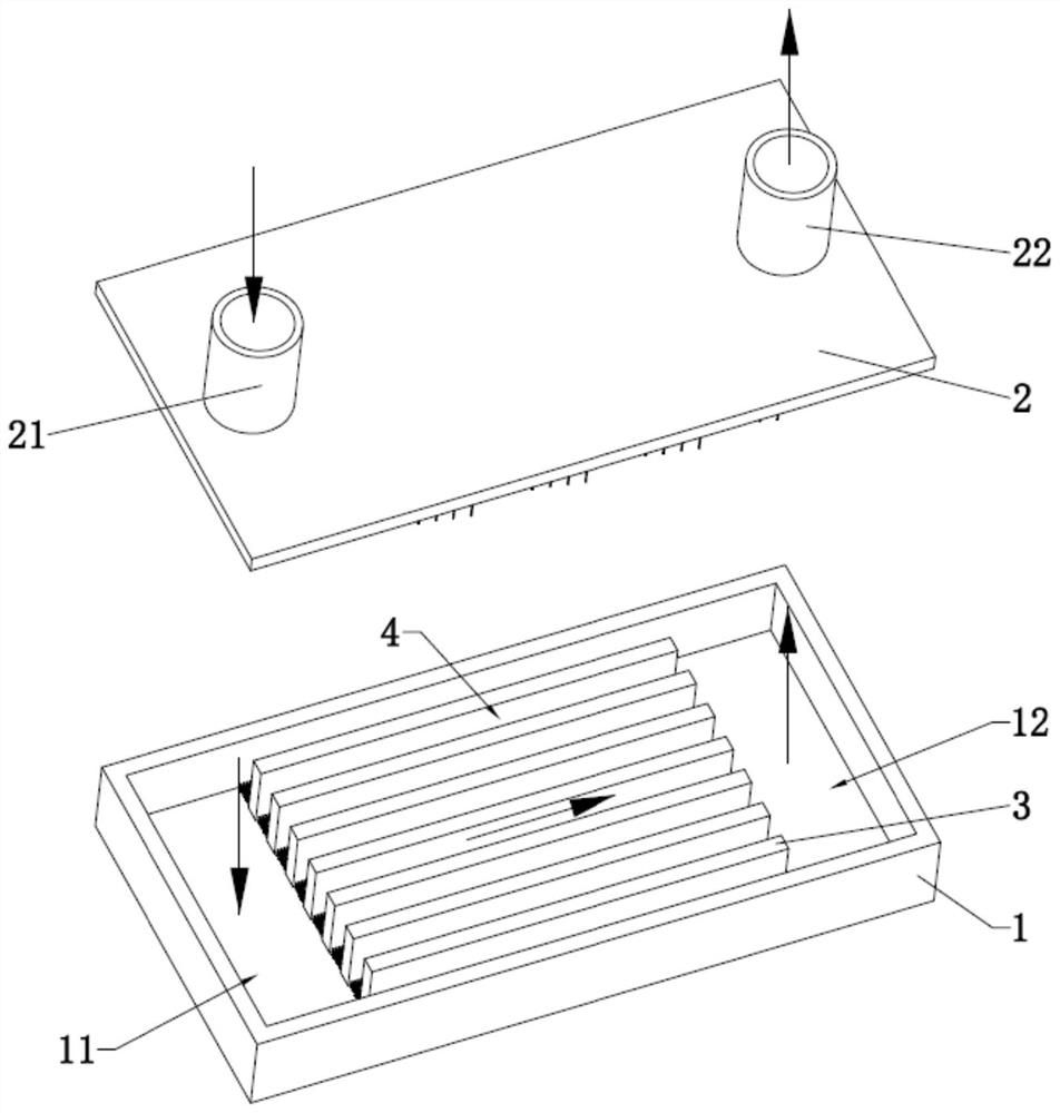
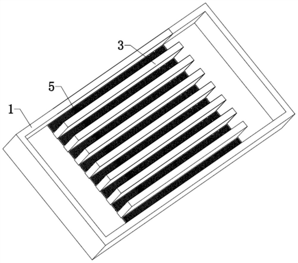
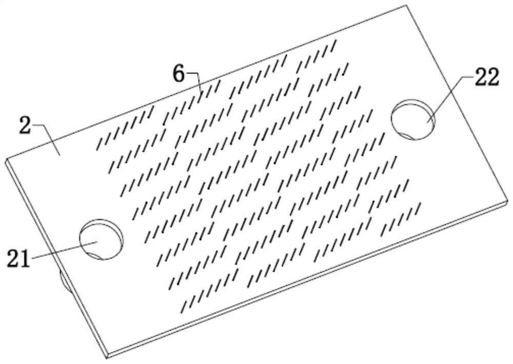
[0028] see figure 1 , figure 2 as well as image 3 As shown, among them, figure 1 is a schematic diagram of a specific structure in an embodiment of the present invention, figure 2 It is a specific structural diagram of the main body in the embodiment of the present invention, image 3 It is a specific structural diagram of the cover plate in the embodiment of the present invention.

[0029] A phase change heat exchanger, comprising a ma...


PUM


Abstract

The invention relates to the technical field of heat dissipation and heat exchangers, and discloses a phase change heat exchanger. The phase change heat exchanger comprises a body, a cover plate and a heat dissipation assembly. The heat dissipation assembly comprises a plurality of heat dissipation parts, the adjacent heat dissipation parts are arranged at intervals to form micro-channels, a plurality of first pin fins are arranged in each micro-channel, and the micro-channels are combined to form a micro-channel area. The body comprises an inlet cavity and an outlet cavity, and the inlet cavity communicates with the outlet cavity through the micro-channel area. The cover plate is provided with an inlet pipe and an outlet pipe, the inlet pipe communicates with the inlet cavity, and the outlet pipe communicates with the outlet cavity. A brand-new micro-channel heat sink is provided mainly from the angles of increasing vaporization cores and enhancing the turbulence degree of fluid in the micro-channels, that is, pin fin structures are arranged on the upper bottom surfaces and the lower bottom surfaces of the micro-channels, so that the flowing boiling stability in the heat exchanger is enhanced, and the cooling and temperature equalizing effects of the heat sink are greatly improved.

Description

technical field [0001] The invention relates to the technical field of heat dissipation and heat exchangers, in particular to a phase-change heat exchanger. Background technique [0002] With the rapid development of Micro-Electro-Mechanical System (MEMS) and micromachining technology, the speed of miniaturization and integration of electronic components is constantly increasing. At the same time, the heating power of electronic components is also increasing, which leads to higher and higher heat flux density. If the heat generated by electronic components cannot be quickly released to the external environment, it will cause its own temperature to rise continuously. However, the stability of electronic components is very sensitive to temperature. Excessive temperature will not only affect electronic components. The stability of the working performance of the components is more serious. When the temperature exceeds the critical value, the electronic components will be burned...

Claims


Application Information

Patent Timeline
Patent Type & Authority Applications(China)
IPC IPC(8): F28D15/02F28F9/22
CPCF28D15/02F28F9/22
Inventor 张衍俊刘珠明陈志涛
Owner GUANGDONG INST OF SEMICON IND TECH
Why Eureka
Try Eureka