Inking or dampening unit including adjustable throw-on force for setting imprint width

a technology of imprint width and throw-on force, which is applied in the direction of rotary lithographic machines, office printing, printing, etc., can solve the problems of complex setting and subsequent adjustment of stops, and achieve the effect of low setting

Inactive Publication Date: 2008-05-13
MANROLANAD AG
View PDF26 Cites 3 Cited by
  • Summary
  • Abstract
  • Description
  • Claims
  • Application Information

AI Technical Summary

Benefits of technology

[0006]It is an object of the invention to provide an inking or dampening unit whic

Problems solved by technology

A disadvantage is the complexity of the set

Method used


Image

  • Inking or dampening unit including adjustable throw-on force for setting imprint width
  • Inking or dampening unit including adjustable throw-on force for setting imprint width
  • Inking or dampening unit including adjustable throw-on force for setting imprint width

Examples


Embodiment Construction

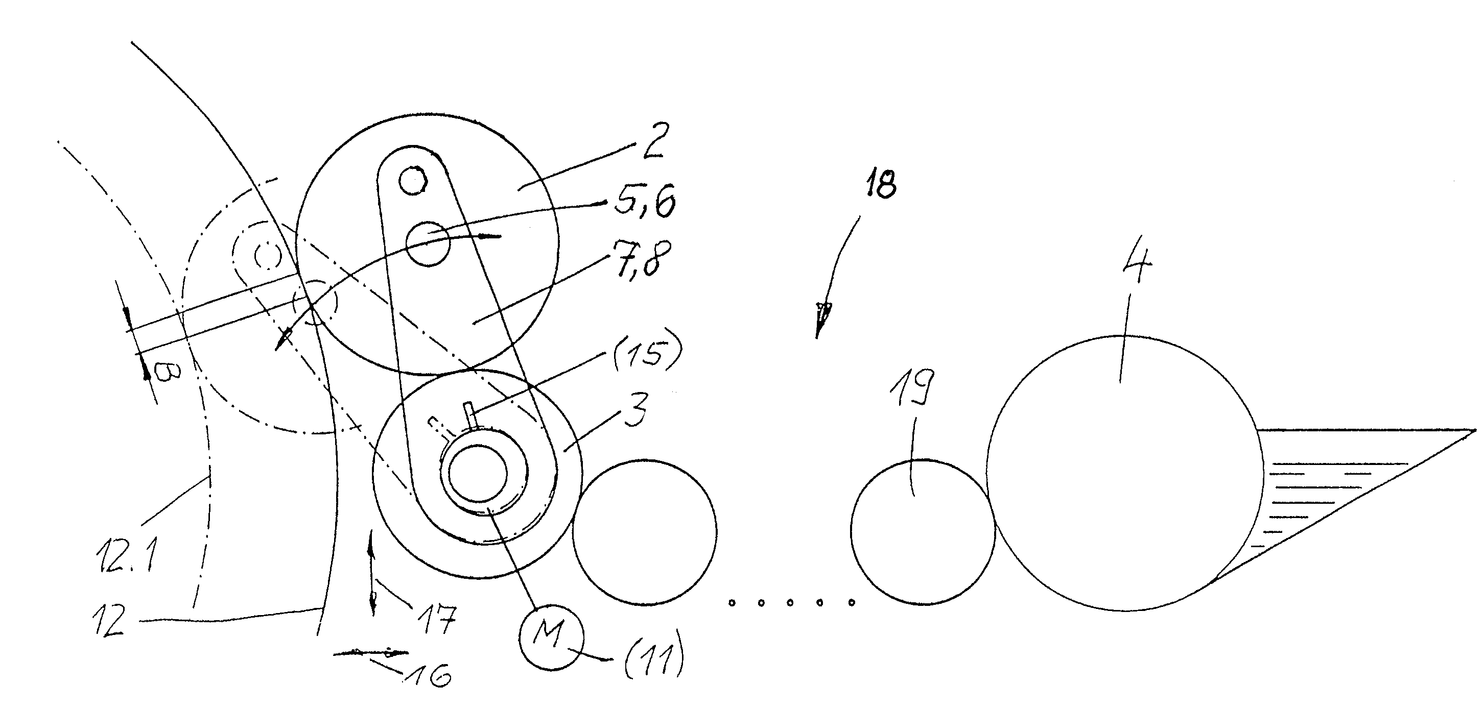
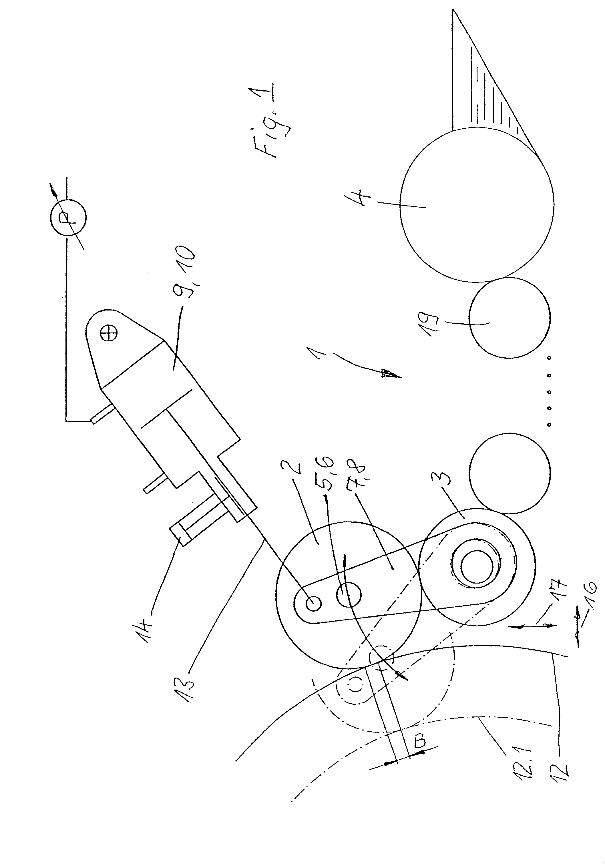
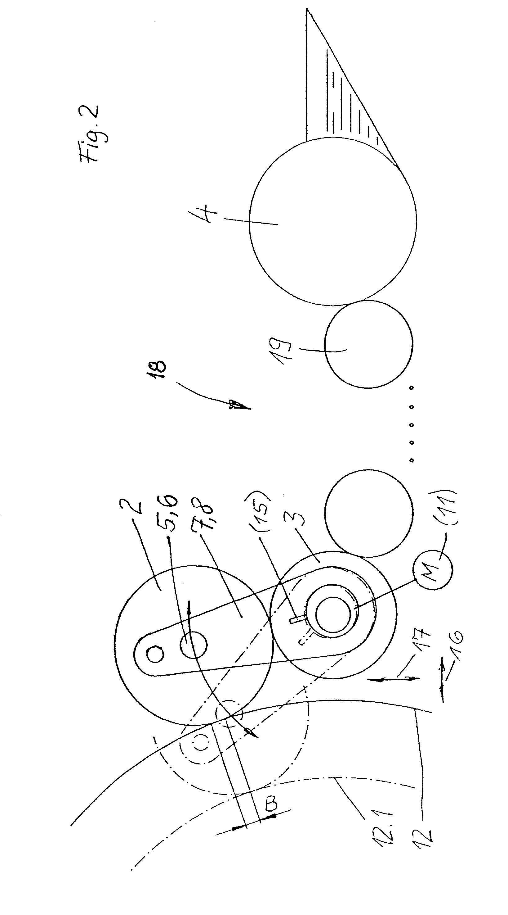
[0016]FIG. 1 shows an inking unit 1, of which only an applicator roll 2 and a distributor cylinder 3 are shown. Furthermore, a wedge-shaped ink fountain 4 is shown, by way of example, as the ink source, ink transport rolls 19 which are only indicated diagrammatically transporting ink from said ink fountain 4 to the distributor cylinder 3.

[0017]The applicator roll 2 is mounted at both ends with its journals 5, 6 in levers 7, 8. The levers 7, 8 can be pivoted about the rotational axis of the distributor cylinder 3. For this purpose, they are mounted, for example, on the journals of the distributor cylinder 3 or in side walls (not shown), in which the distributor cylinder 3 is also mounted.

[0018]In each case one linear motor in the form of an operating cylinder 9, 10 acts in a pivotably mounted manner on the levers 7, 8. A spring or an electric attraction magnet, for example, could also be used as linear motor 22 as shown in FIG. 3. Instead of by means of operating cylinders 9, 10 or l...


PUM


Abstract

An inking or dampening unit includes an applicator roll mounted on levers so that the application roll can be pivoted about a distributor cylinder onto a form cylinder with a controlled throwing-on force.

Description

PRIORITY CLAIM[0001]This is a U.S. national stage of application No. PCT / EP03 / 03455, filed on 3 Apr. 2003. Priority is claimed on that application and on the following application(s): Country: Germany, Application No.: 102 15 422.8, Filed: 8 Apr. 2002.BACKGROUND OF THE INVENTION[0002]1. Field of the Invention[0003]The invention relates to an inking or dampening unit of a rotary press, having at least one applicator roll pivotally mounted on levers so that the applicator roll is pivotable onto a form cylinder of the rotary press.[0004]2. Description of the Prior Art[0005]GB 2132944 discloses an inking unit, in which an ink applicator roll can be pivoted about a distributor cylinder and can be thrown onto a form cylinder at the same time. The applicator roll is mounted on both sides in levers. Adjustable stops against which the levers can be moved serve to adjust the applicator roll on the form cylinder. A disadvantage is the complexity of the setting and subsequent adjustment of the ...

Claims


Application Information

Patent Timeline
IPC IPC(8): B41F31/32B41F7/26B41F31/18B41F31/30B41F31/36B41F33/10
CPCB41F31/301B41F31/36
Inventor BACHMEIR, XAVER
Owner MANROLANAD AG
Why Eureka
Try Eureka