Micro gas generator

a gas generator and micro-gas technology, applied in the direction of pedestrian/occupant safety arrangements, transportation and packaging, vehicular safety arrangements, etc., can solve the problems of increasing the exposure of gas generant, increasing the risk of gas generant leakage, so as to reduce the amount of gas generant exposed and low cost

Inactive Publication Date: 2008-05-13
AUTOMOTIVE SYST LAB
View PDF10 Cites 26 Cited by
  • Summary
  • Abstract
  • Description
  • Claims
  • Application Information

AI Technical Summary

Benefits of technology

[0007]A gas generator is provided, comprising an initiator including an initiator charge, a gas generant composition spaced apart from the initiator, and a fluid-impermeable blast director interposed between the initiator and the gas generant composition. The blast director provides a barrier between the gas generant composition and a blast resulting from ignition of the initiator charge when the initiator charge is ignited. The blast director, when used with particular gas generant configurations, reduces the effects of the initiator blast and reduces the amount of gas generant exposed to the blast, enabling the structural integrity of a pre-formed gas generant insert to be maintained. The blast director disclosed herein is a simple, low cost solution to the problem of preventing blast damage to a shaped gas generant insert. A particular (but not restrictive) application of the gas generator disclosed herein is in a micro gas generator (MGG), wherein the gas generant is a single cylindrical piece housed in a casing.

Problems solved by technology

With the advent of non-azide compositions, however, relatively higher burn rates often require a relatively lower aggregate gas generant surface area.
In cases where the gas generant insert is in direct communication with the initiator during initiator activation, flame and ignition products from the initiator may fracture the gas generant insert.
In addition, the sizes of the resulting gas generant cast fragments are unpredictable.
These factors contribute to ballistic variability, making it difficult to control and predict the inflation characteristics of the gas generator.
Devices such as seatbelt pretensioners require a low initial pressurization and slow starting gas generation.
However, it can be expensive and / or inconvenient to reduce the initiator charge mass in order to reduce the likelihood of gas generant cast fracture.

Method used


Image

  • Micro gas generator
  • Micro gas generator
  • Micro gas generator

Examples


Embodiment Construction

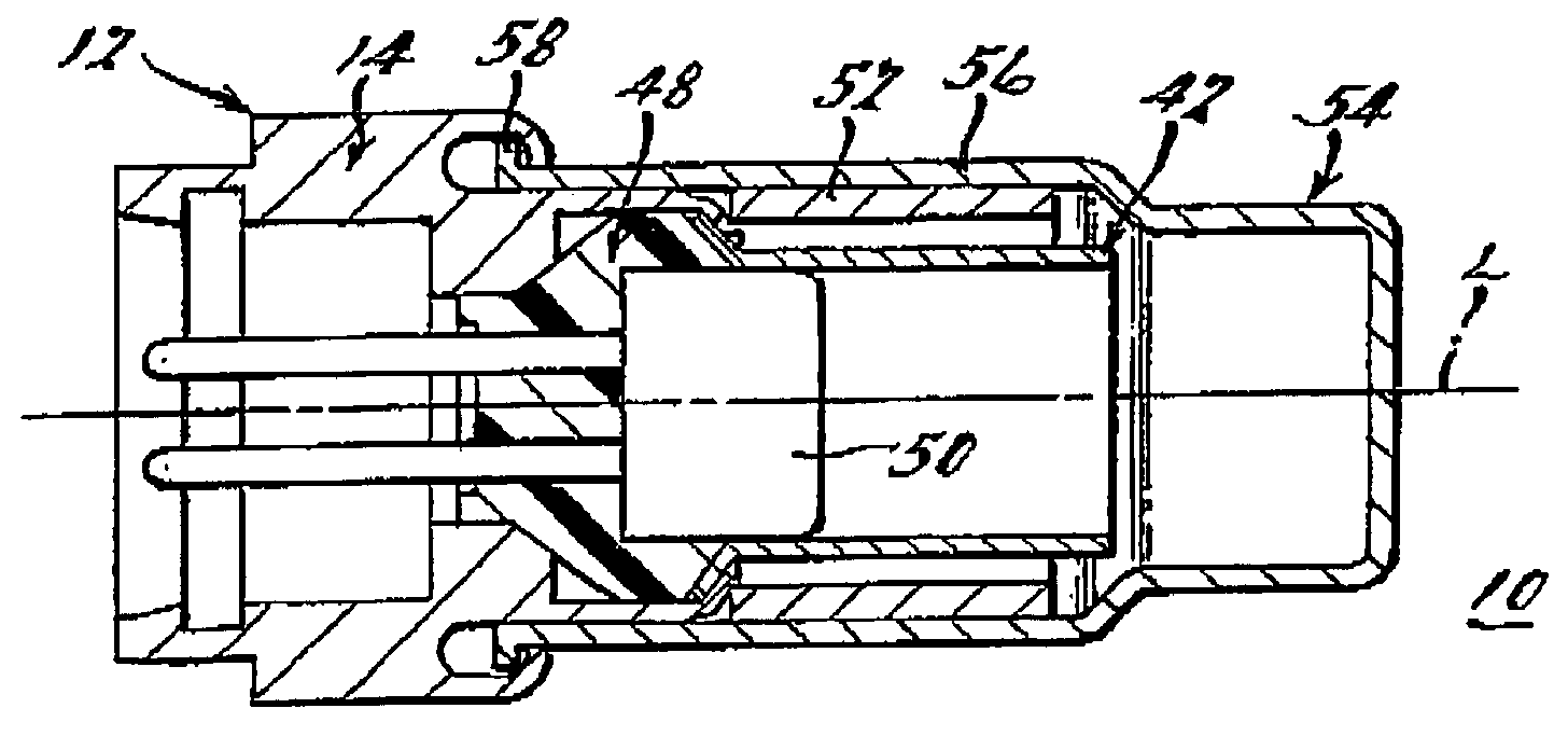
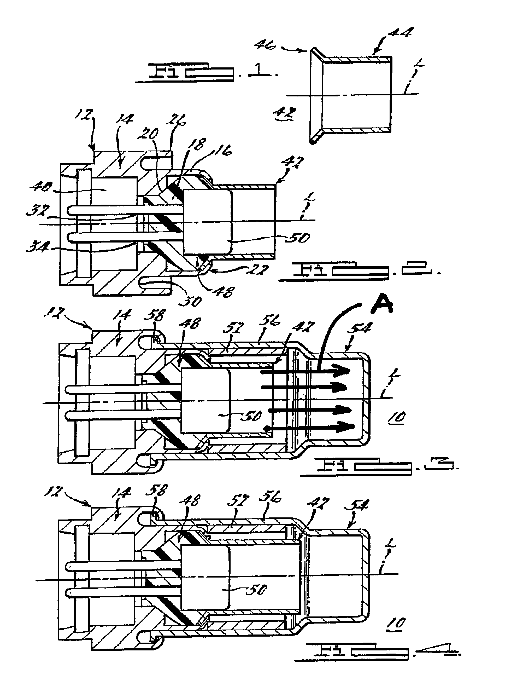
[0018]FIGS. 1-3 show a gas generator incorporating an initiator blast director in accordance with the present invention. Gas generator 10 includes an initiator holder 12 for receiving and securing an initiator 48 therein. Holder 12 includes a body 14 and an annular wall 16 extending from body 14 to define a cylindrical cavity 18. An annular shoulder 20 is formed in the interior of cavity 18. A plurality of first crimp tabs 22 are formed along an edge 24 of wall 16. A plurality of second crimp tabs 26 extend along an outer edge 28 of body 14. An annular groove 30 is formed in body 14 along a base of wall 16, between wall 16 and second crimp tabs 26. Holder 12 also has a pair of axially extending holes 32, 34 through which initiator electrodes extend. A rear portion of holder 12 is configured to provide an interface mateable with a complementary connector of a wiring harness or other suitable initiator activation signal transmission medium. Holder 12 is formed from a metal or metal al...


PUM


Abstract

A gas generator (10) is provided, comprising an initiator (48) including an initiator charge, a gas generant insert (52) spaced apart from the initiator (48), and a fluid-impermeable blast director (42) interposed between the initiator (48) and the gas generant insert (52). The blast director (42) provides a barrier between the gas generant insert (52) and a blast resulting from ignition of the initiator charge when the initiator charge is ignited. The blast director (42), when used with particular gas generant configurations, reduces the effects of the initiator blast and reduces the amount of gas generant exposed to the blast, enabling the structural integrity of the gas generant (52) to be maintained.

Description

CROSS REFERENCE TO RELATED APPLICATIONS[0001]This application claims the benefit of provisional application Ser. No. 60 / 625,351, filed on Nov. 5, 2004.BACKGROUND OF THE INVENTION[0002]The present invention relates generally to gas generating systems and, more particularly, to gas generators used in vehicle occupant protection systems and related components, such as seatbelt pretensioners.[0003]Gas generators used in seatbelt pretensioners are known as micro gas generators due to the relatively small size of the gas generator. Exemplary pretensioners using such micro gas generators include those described in U.S. Pat. Nos. 6,460,794, 6,505,790, 6,520,443, and 6,419,177, incorporated herein by reference. Micro gas generators generally contain an initiator including an initiator charge, an initiator retainer, and a gas generant composition which ignites and burns in response to ignition of the initiator to produce gases for actuating the seatbelt pretensioner.[0004]In some micro gas ge...

Claims


Application Information

Patent Timeline
Patent Type & Authority Patents(United States)
IPC IPC(8): B60R21/26
CPCB60R22/4633F42B3/04F42B3/22B60R2021/26029
Inventor STEVENS, BRUCE A.
Owner AUTOMOTIVE SYST LAB
Why Eureka
Try Eureka