
Synchronizer for slide-out room

a technology for synchronizing slides and slides, which is applied in the direction of transportation and packaging, transportation items, vehicle sanitation, etc., can solve the problems of uneven slide-out conditions, increased mechanism life, and movement of the top of the slide-out room relative to the bottom

Active Publication Date: 2008-05-13
IND AXLE CO LLC
View PDF4 Cites 22 Cited by
  • Summary
  • Abstract
  • Description
  • Claims
  • Application Information

AI Technical Summary

Benefits of technology

[0010]It is a further object of the present invention to provide a synchronizing mechanism for evenly sliding out a slide-out room of a vehicle.
[0011]It is yet a further object of the present invention to provide a mechanism that may unevenly extend or retract a slide-out room from a vehicle but synchronizing this uneven movement while it occurs.
[0012]It is yet a further object of the present invention to provide a synchronizing mechanism that secures the position of an upper area of a slide-out room, preventing the slide-out room from unsealing from the vehicle.

Problems solved by technology

As a result, there is typically adequate space within the vehicle's interior to accommodate users in transit and remain within the standard width limitations imposed upon a vehicle.
Moreover, heavy-duty gearing used in such a design typically increases the lifespan of the mechanism.
Yet, with this type of gearing design most of the motive force is concentrated and exerted at the bottom of the room.
This localized load on the bottom surface of the room can often create uneven slide-out conditions between the slide-out room's bottom portion (where the load is concentrated) and the top portion (where there is very little load).
Furthermore, due to the size of some slide-out rooms, the top of the slide-out room may be caused to move relative to bottom if pushed, bumped, or otherwise moved due to the “play” that exists in this type of gearing design.
Thus, dirt, water or other undesirable elements may enter the vehicle body thus making the vehicle interior unsightly or even causing damage.
At times, however, uneven extension or retraction of a slide-out room has been designed into the slide-out mechanism.

Method used


Image

  • Synchronizer for slide-out room
  • Synchronizer for slide-out room
  • Synchronizer for slide-out room

Examples


Embodiment Construction

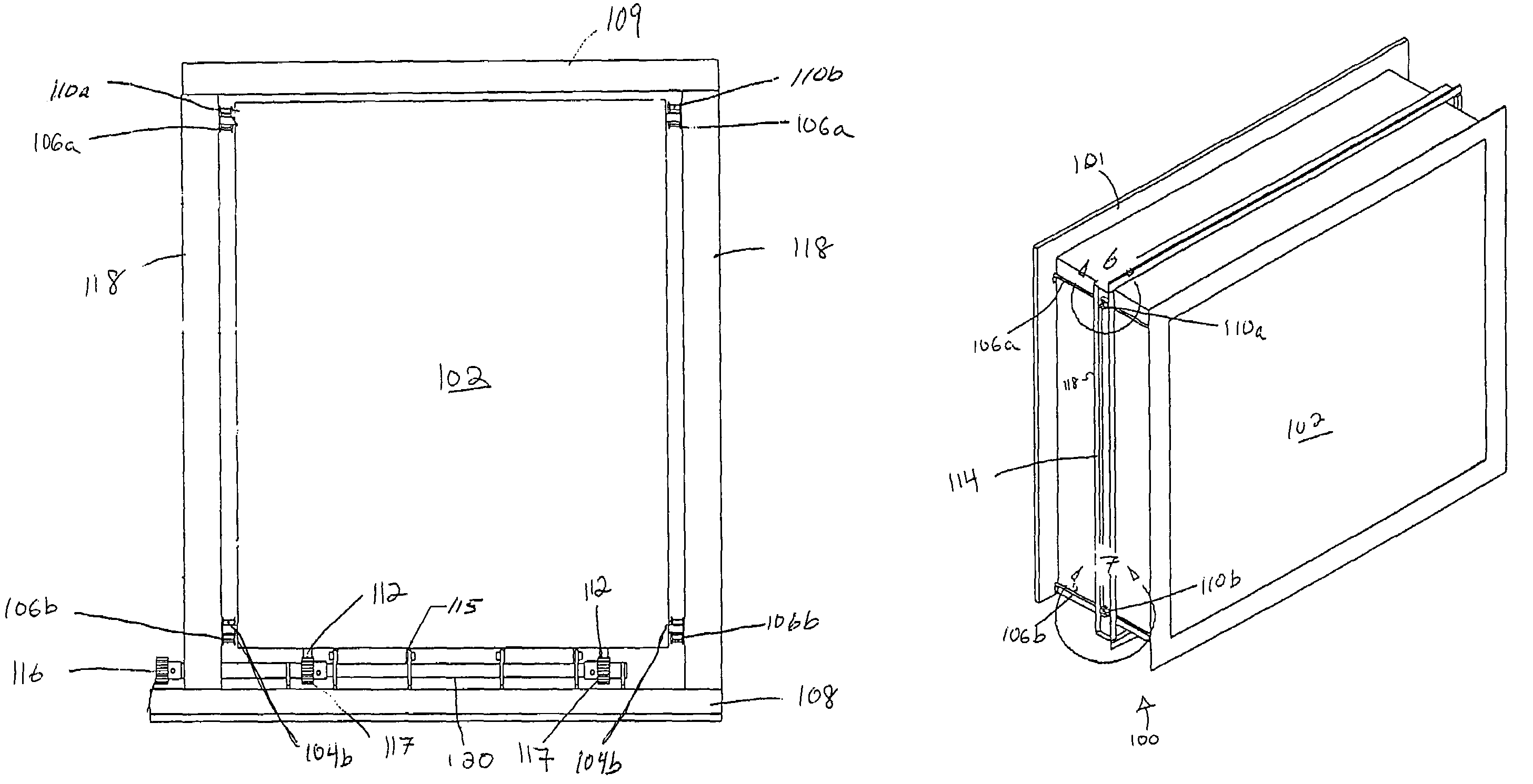
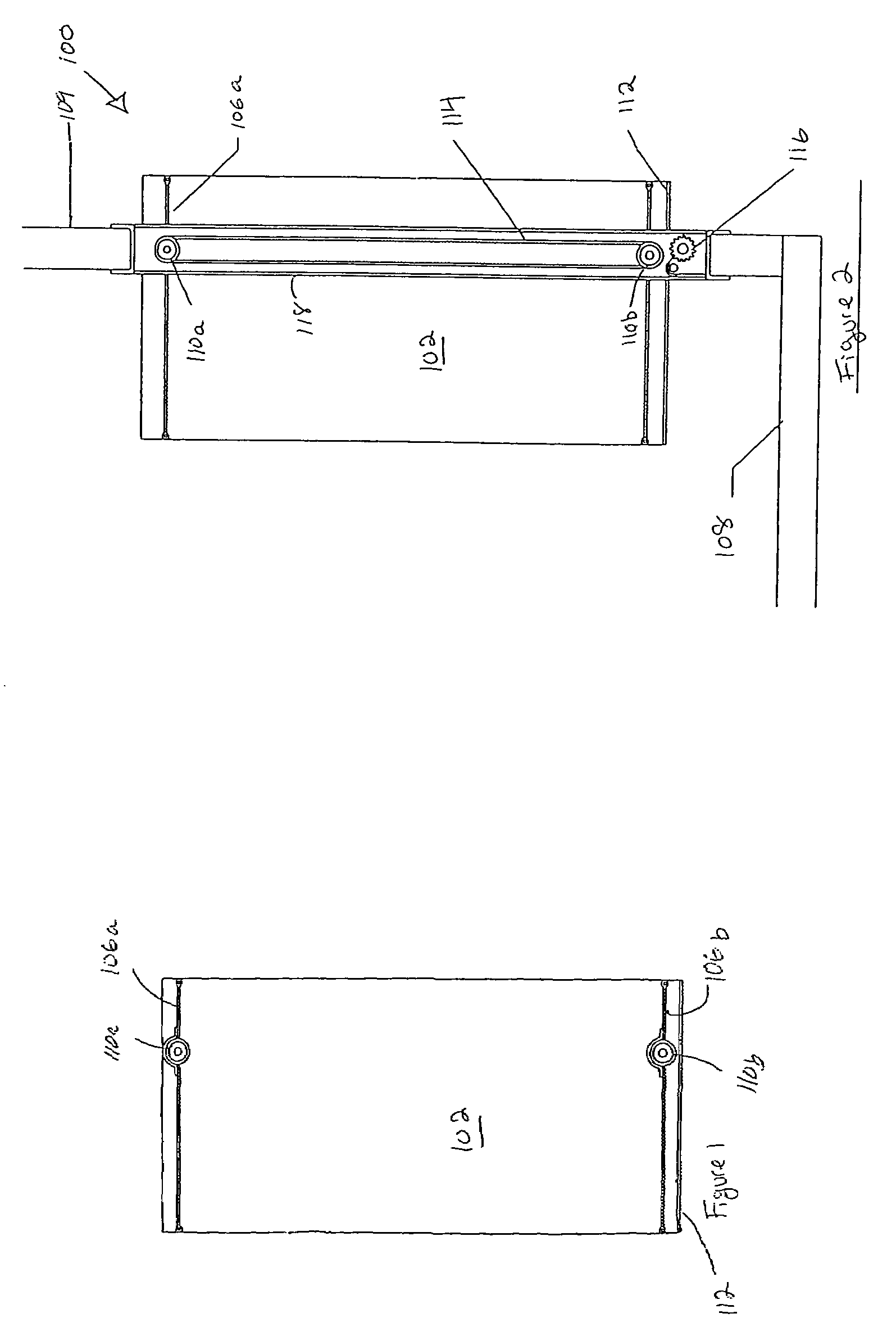
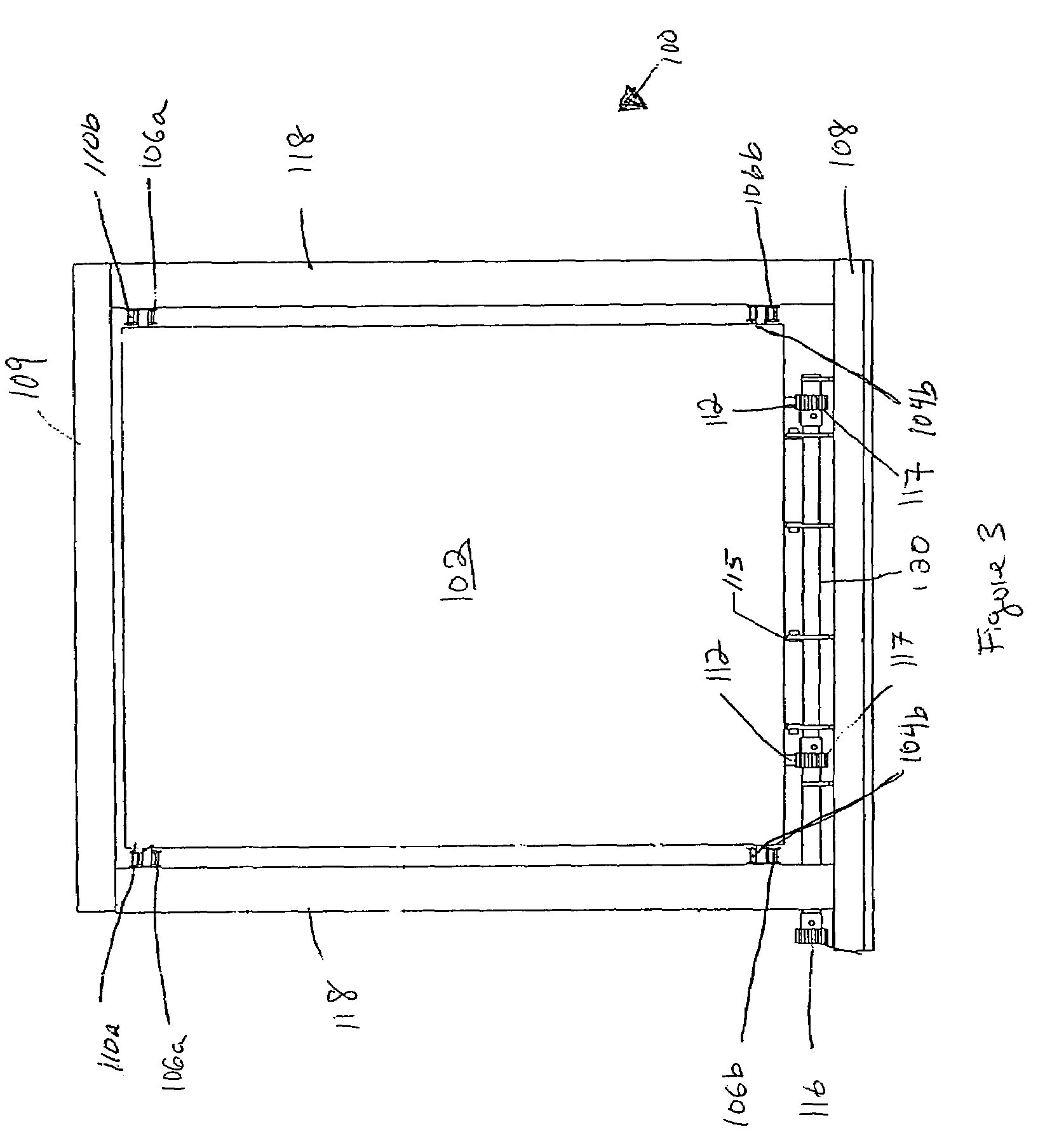
[0029]FIGS. 1-10 illustrate a preferred embodiment of a slide-out room synchronizer 100 according to the present invention. The slide-out room synchronizer 100 includes upper and lower timing belts 106a and 106b on each side of the slide-out room 102. The sidewall 118 of vehicle or trailer includes an upper and a lower timing gear 110a and 110b on each side that engage with the upper and lower timing belts 106a and 106b. The rotational movement of upper and lower timing gears 110a and 110b are synchronized by a synchronizing belt 114, which transfers any movement of the lower region of the slide-out room 102 to the upper region. Thus, the slide-out room synchronizer 100 synchronizes movement between the upper and lower regions of the slide-out room 102.

[0030]Looking to FIGS. 1 and 2, a side view of the slide-out room 102 according to the present invention can be seen. Upper and lower timing belts 106a and 106b are fixed across the upper and lower sides of the slide-out room 102 resp...


PUM


Abstract

The present invention provides a slide-out room synchronizing mechanism. In one preferred embodiment according to the present invention, the slide-out room synchronizer includes upper and lower timing belts fixed to the side of the slide-out room. Each belt is coupled to a synchronizing belt within the vehicle by a set of connecting gears. As the bottom of the slide-out room moves, the force is transferred through the gears and synchronizing belt to the top upper timing belts. In this respect, the movement of the top of the slide-out room is synchronized to the bottom, providing synchronized extension or retraction at equal or varying speeds.

Description

CROSS REFERENCE TO RELATED APPLICATIONS[0001]This application claims priority to U.S. Provisional Application 60 / 508,456, entitled Belt-Gear Above Floor Slide, filed Oct. 3, 2003 the entire contents of which are hereby incorporated by reference.FIELD OF INVENTION[0002]This invention relates broadly to slide-out rooms. More particularly, this invention relates to a mechanism for synchronizing movement of an upper and lower region of a slide-out room for a vehicle (motor home), travel trailer, fifth wheel travel trailer, and other recreational travel vehicles.BACKGROUND OF THE INVENTION[0003]In order to increase the available interior space of a motorized or towable vehicle such as a motor home or trailer, these vehicles have been designed to include slide-out rooms. When the vehicle is in transit, the slide-out room is retracted and stored in the vehicle's interior with the exterior wall of the slide-out room approximately flush with the vehicle's exterior. As a result, there is typi...

Claims


Application Information

Patent Timeline
Patent Type & Authority Patents(United States)
IPC IPC(8): B60D3/00
CPCB60P3/34
Inventor BLODGETT, JR., RAY W.
Owner IND AXLE CO LLC
Learn More