
Projector

a projector and light source technology, applied in the field of projectors, can solve the problems of damage to the light source and harm to the display performance of the projector

Active Publication Date: 2008-05-13
YOUNG OPTICS
View PDF3 Cites 4 Cited by
  • Summary
  • Abstract
  • Description
  • Claims
  • Application Information

AI Technical Summary

Benefits of technology

[0009]An objective of the present invention is to provide a projector, which is capable of preventing an invisible light beam and a visible light beam back to a light source of the projector to protect the light source from damages causing from high temperature and maintain a display performance of the projector.

Problems solved by technology

A weighty issue of the projector is a heat from the light source 4.
This high temperature causes a damage on the light source 4 and harms the display performance of the projector 2.

Method used


Image

  • Projector
  • Projector
  • Projector

Examples


Embodiment Construction

[0024]The present invention will become more fully understood from the detailed description given hereinbelow and the accompanying drawings which are given by way of illustration only, and thus are not limitative of the present invention.

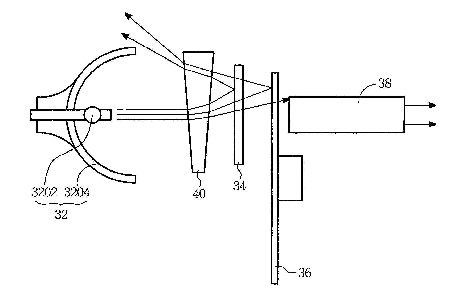
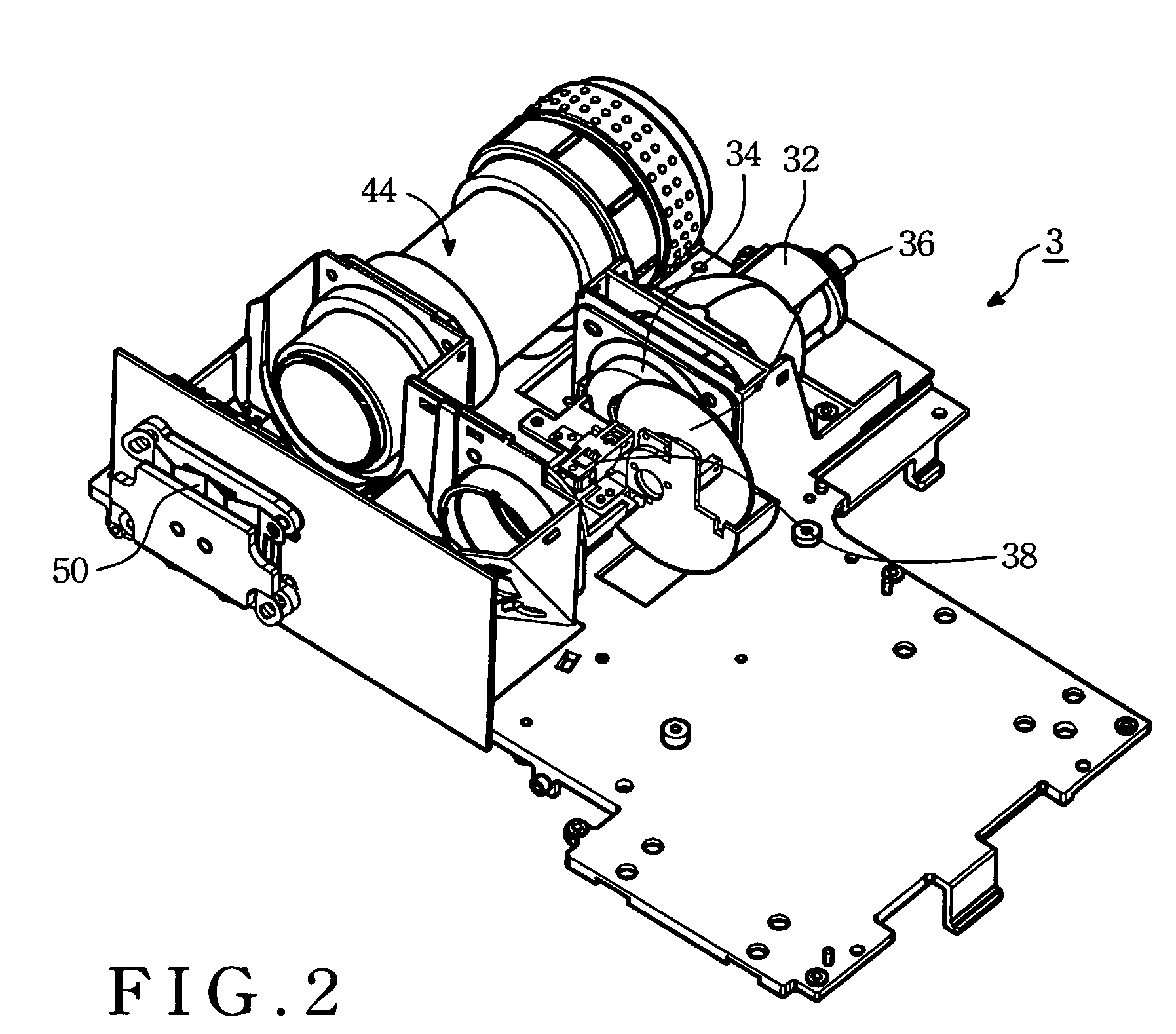
[0025]Please refer to FIG. 2, which illustrates a projector 3 according to the present invention. The projector 3 comprises a light source 32, an Ultraviolet / Infrared Radiation (UV / IR) filter 34, a color wheel 36, an integration rod 38, a light valve 50, and a projection lens 44.

[0026]Please refer to FIG. 3. The light source 32 comprises a lamp 3202 and a lamp reflector 3204. The lamp 3202 provides a light beam. The lamp reflector 3204 guides the light beam provided by the lamp 3202 to the color wheel 36.

[0027]The UV / IR filter 34 is disposed between the light source 32 and the color wheel 36 in this embodiment. The UV / IR filter 34 transmits a visible light beam of the light beam and reflects an invisible light beam of the light beam. The invisible l...


PUM


Abstract

A projector comprises a light source, an Ultraviolet / Infrared Radiation (UV / IR) filter, a color wheel and means for guiding the light beam reflected by the color wheel toward directions away from the light source. The light source is for providing a light beam. The UV / IR filter is disposed with a tilt angle ranging from 13 degrees to 30 degrees. The color wheel for receiving the light beam transmits a primary color light beam of the light beam in a predetermined time section, and the other color light beam of the light beam is reflected by the color wheel. The means for guiding the light beam reflected by the color wheel toward directions away from the light source further guide a invisible light beam of the light beam reflected from the UV / IR filter.

Description

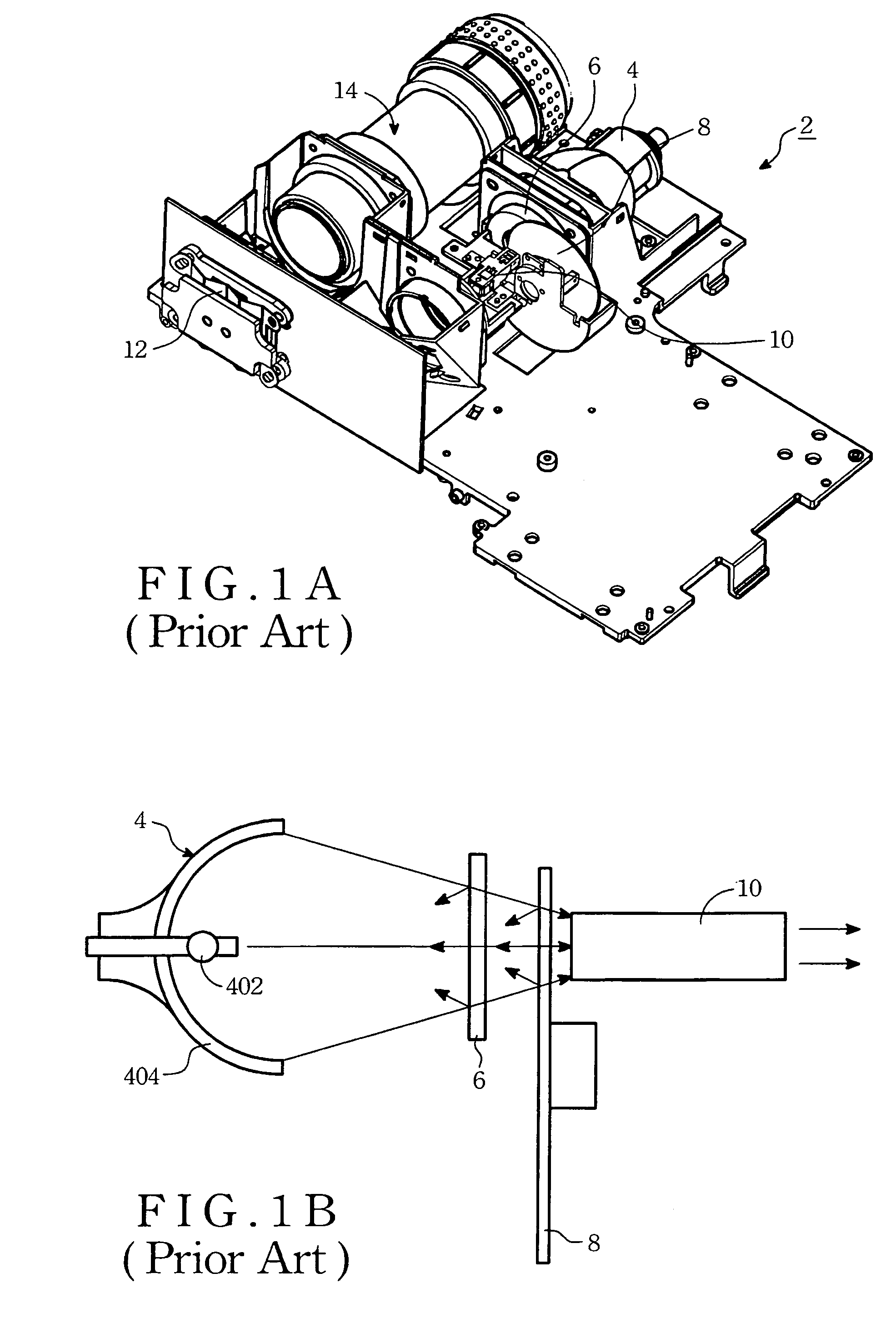
BACKGROUND OF THE INVENTION[0001](1) Field of the Invention[0002]The present invention generally relates to a projector, and particularly relates to a projector for reducing a temperature of a light source.[0003](2) Description of the Prior Art[0004]Please refer to FIG. 1A, which is illustrating a conventional projector 2. The conventional projector 2 comprises a light source 4, an Ultraviolet / Infrared Radiation (UV / IR) filter 6, a color wheel 8, an integration rod 10, a light valve 12, and a projection lens 14.[0005]Please refer to FIG. 1B, which is illustrating a light path of the conventional projector according to FIG. 1A. The light source 4 comprises a lamp 402 for providing a light beam and a lamp reflector 404. The lamp reflector 404 guides the light beam toward the UV / IR filter 6. The UV / IR filter 6 transmits a visible light beam of the light beam and reflects an ultraviolet (UV) and an infrared radiation (IR) of the light beam.[0006]The visible light beam-passes through the...

Claims


Application Information

Patent Timeline
Patent Type & Authority Patents(United States)
IPC IPC(8): F21V9/00
CPCH04N9/3114H04N9/315G03B21/2086
Inventor CHENG, CHU-MINGYUN, CHI-CHUI
Owner YOUNG OPTICS
Learn More