

Backlight module and electronic device
A technology of backlight module and light source, applied in the field of communication, can solve the problems of increasing LCD mobile terminals, low fingerprint identification accuracy, uneven display image, etc., and achieve the effect of maintaining display effect and realizing accurate identification and verification.
- Summary
- Abstract
- Description
- Claims
- Application Information
AI Technical Summary
Problems solved by technology
Method used
Image

Examples
Embodiment 1
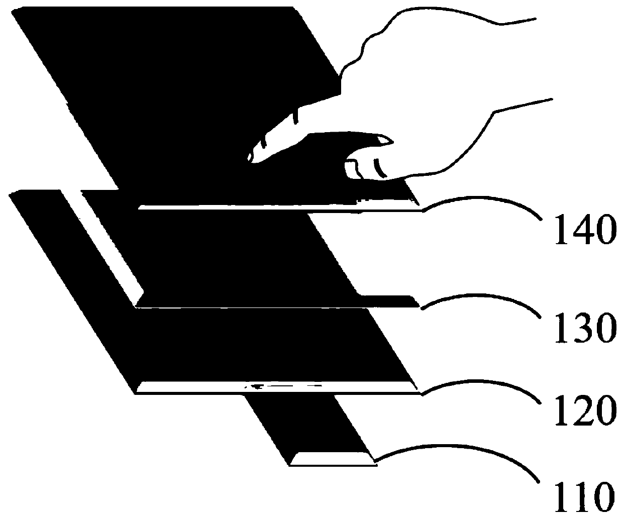
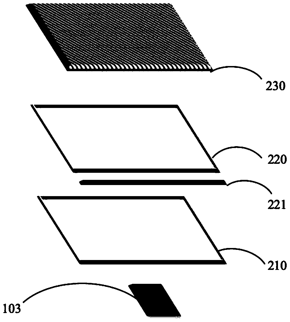
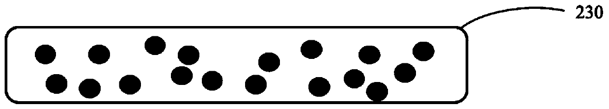
[0025] First, through figure 2 , image 3 , the backlight module of Embodiment 1 of the present invention will be described. According to the backlight module of Embodiment 1 of the present invention, the backlight module includes a light source 221 and a light guide plate 220 disposed on one side of the light source 221, a reflective sheet 210 disposed below the light guide plate 220, and an infrared transparent film disposed above the light guide plate 220. Diffusion film 230, and the fingerprint identification device 103 that is arranged under the infrared transparent diffusion film 230 and the reflection sheet 210, to identify the biological fingerprint optical signal; wherein, the infrared transparent diffusion film 230 contains evenly distributed CdO nanoparticles, and its particle diameter is about 20nm, such as image 3 As shown in the cross-sectional structure diagram of the infrared transparent diffusion film, CdO nanoparticles emit light in the form of non-direct...
Embodiment 2
[0031] Please refer to Figure 4 , is a cross-sectional structure view of the backlight module based on the infrared transparent diffusion film according to the second embodiment of the present invention. The differences between Embodiment 2 and Embodiment 1 will be described below, and the similarities will not be repeated here. The fingerprint identification device is disposed between the light guide plate 220 and the reflector 210 .
Embodiment 3
[0033] Please refer to Figure 5, is a cross-sectional structure view of the backlight module based on the infrared transparent diffusion film according to the third embodiment of the present invention. Only the differences between Embodiment 3 and Embodiment 1 will be described below, and the similarities will not be repeated here. The fingerprint identification device is disposed between the light guide plate 220 and the infrared transparent diffusion film 230 .
PUM
| Property | Measurement | Unit |
|---|---|---|
| Particle size | aaaaa | aaaaa |
Abstract
Description
Claims
Application Information