Fingerprint recognition module and electronic equipment

A fingerprint identification module and fingerprint identification technology, applied in the field of communication, can solve the problems of poor light directivity and achieve the effects of maintaining luminous brightness and uniformity, reducing divergence, and improving directivity

Inactive Publication Date: 2020-01-24
SHENZHEN LONGLI TECH CO LTD
View PDF15 Cites 2 Cited by
  • Summary
  • Abstract
  • Description
  • Claims
  • Application Information

AI Technical Summary

Problems solved by technology

However, when the incident light enters these multi-microlayer structure materials, it passes through a series of light refraction and reflection, and the outgoing light diverges in a large spatial range, which makes the light directivity poor.

Method used


Image

  • Fingerprint recognition module and electronic equipment
  • Fingerprint recognition module and electronic equipment
  • Fingerprint recognition module and electronic equipment

Examples


Embodiment 1

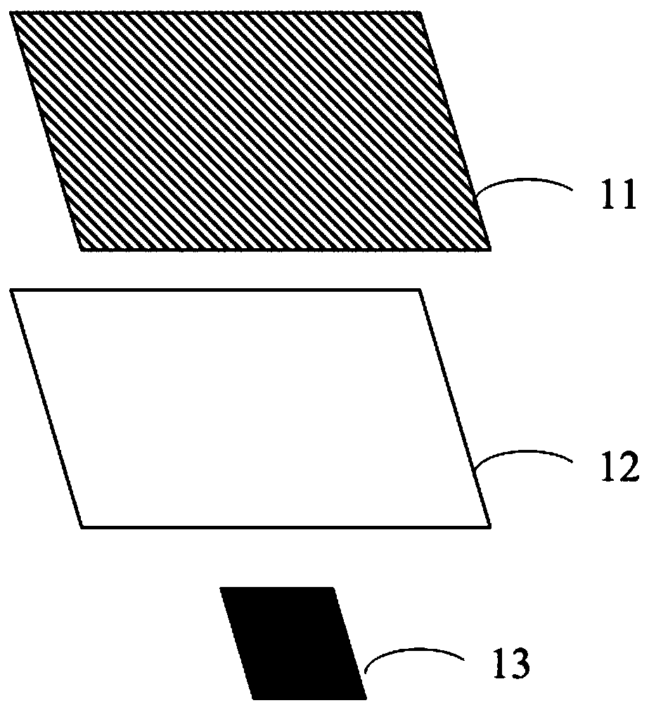
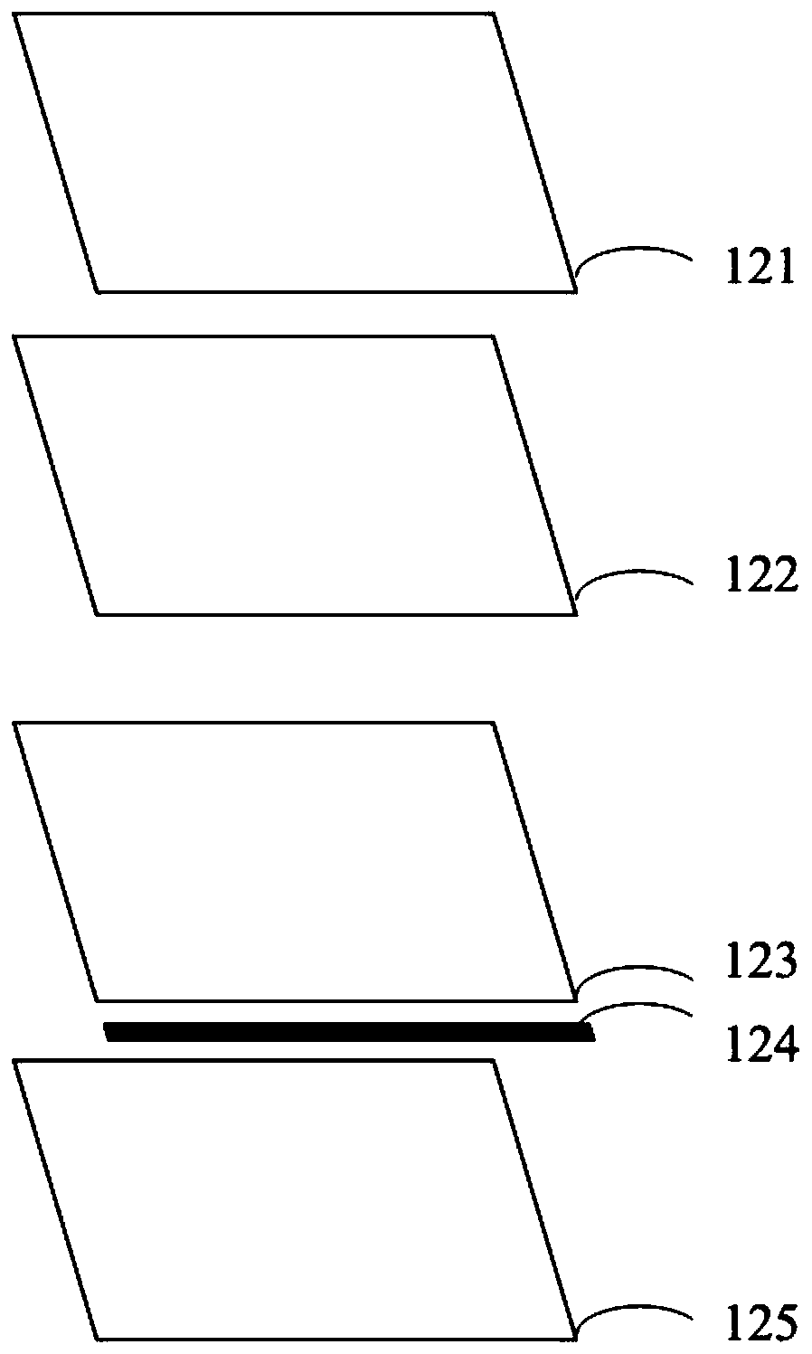
[0031] First, please refer to Figure 1-3, the fingerprint identification module of Embodiment 1 of the present invention will be described. According to the fingerprint identification module of Embodiment 1 of the present invention, it includes an LCD display module and a fingerprint identification device 13 to identify optical signals of biological fingerprints; wherein, the LCD display module includes an LCD display screen 11 and a backlight module 12; the backlight module The set includes a light source 124, a light guide plate 123 arranged on one side of the light source 124, a reflective sheet 125 arranged below the light guide plate 123, a diffusion sheet 122 arranged above the light guide plate 123, and a diffuser sheet 122 arranged on the diffuser The prism sheet 121 above the sheet.

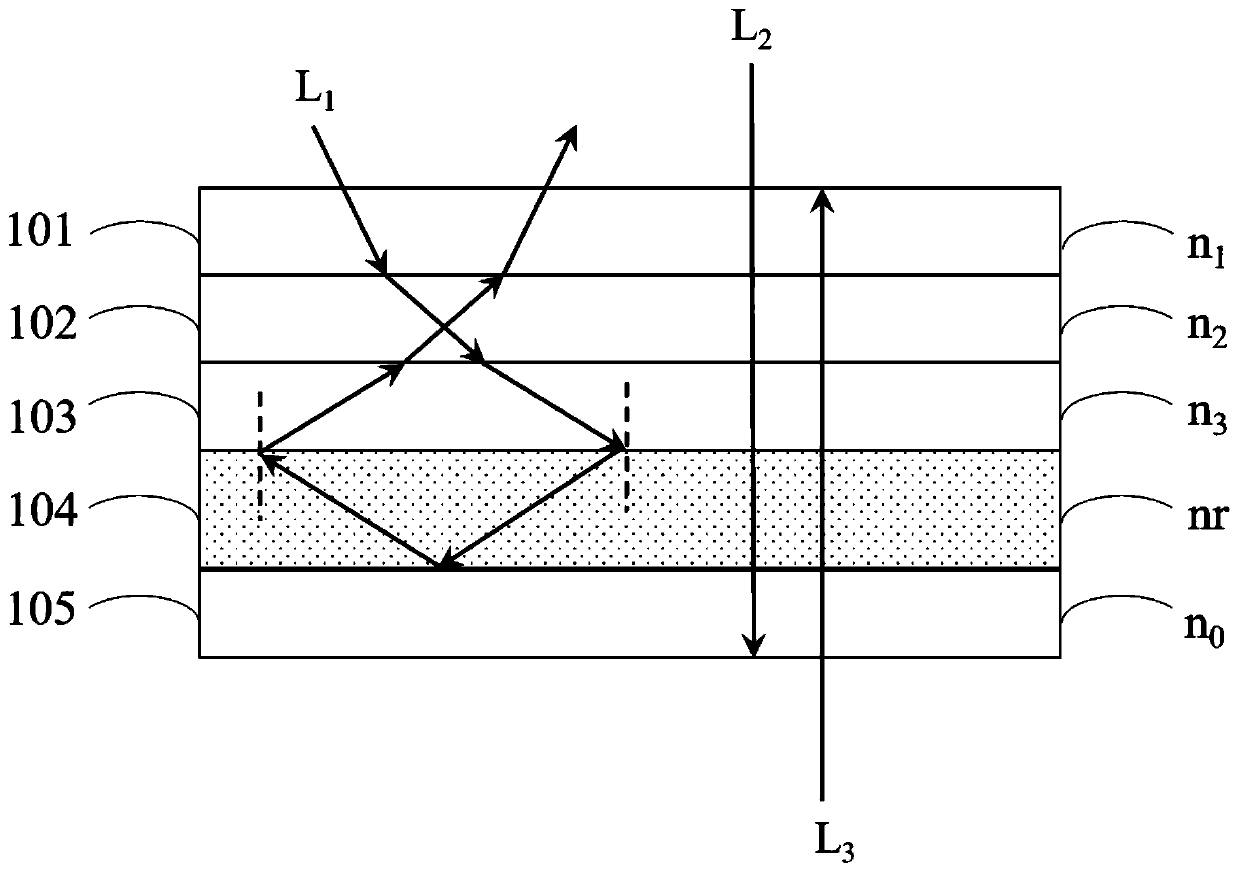
[0032] image 3 It is a cross-sectional view of a reflective sheet in Example 1 of the present invention, which includes a stack of four positive refractive index microlayers 101, 102...

Embodiment 2

[0039] Please refer to Figure 4 , is a cross-sectional view of the reflective sheet of the fingerprint identification module according to Embodiment 2 of the present invention. Only the differences between Embodiment 2 and Embodiment 1 will be described below. Figure 4 The structure of the reflector comprises five layers of positive refractive index microlayers respectively 201, 202, 203, 205, 206 and one layer of negative refractive index microlayers 204. The upper surface of the positive refractive index microlayer 201 is the first surface. The lower surface of the positive refractive index microlayer 206 is the second surface. In Example 2 of the present invention, the effect of light L1 passing through a multi-layer laminate with different positive refractive index microlayers and negative refractive index microlayers is as follows: Figure 4 shown. The negative index microlayer 204 exhibits a refractive index nr for visible light. The first surface arranged in paral...


PUM


Abstract

The invention discloses a fingerprint recognition module. The fingerprint recognition module comprises an LCD (liquid crystal display) module and a fingerprint recognition device to recognize a biological fingerprint optical signal, wherein the LCD module comprises an LCD screen and a backlight module; the backlight module comprises a light source, a light guide plate arranged at one side of the light source, a reflection sheet arranged below the light guide plate, a diffusion sheet arranged above the light guide plate and a prismatic lens arranged above the diffusion sheet; and the reflectionsheet is an optical thin film of a multilayer structure and comprises a first surface, a second surface and a stack of N positive refractive index micro-layers, wherein the first surface and the second surface are arranged in parallel, the second surface is arranged opposite to the first surface, the refractive indexes of N-1 positive refractive index micro-layers from the first surface to the second surface are sequentially and progressively decreased, the refractive index of the Nth positive refractive index micro-layer is greater than the refractive index of the (N-1)th positive refractiveindex micro-layer, and at least one negative refractive index micro-layer is arranged between the N positive refractive index micro-layers from the first surface to the second surface.

Description

technical field [0001] The invention relates to the field of communication technology, in particular to a fingerprint recognition module and electronic equipment used for fingerprint recognition in an LCD screen. Background technique [0002] At present, multi-layer reflective sheets are often used in visual display systems such as liquid crystal displays, and are currently found in electronic devices such as mobile phones, computers and some flat-panel TVs. These systems use liquid crystal (LCD) panels that are backlit by an extended area backlight. A multi-layer reflective sheet coated with Ag reflective coating or Al reflective coating is placed above the backlight or compounded in the backlight to transmit the light of a polarization state emitted by the backlight that can be used by the LCD panel. to the LCD panel. However, optical signals, especially visible light and infrared light, cannot pass through the reflector and be collected under the backlight and the backl...

Claims


Application Information

Patent Timeline
Patent Type & Authority Applications(China)
IPC IPC(8): G02F1/13357G02F1/1333G06K9/00G06F1/16
CPCG02F1/133615G02F1/13338G06F1/1684G06V40/13
Inventor 张小齐刘政曾晓虎黄小芸
Owner SHENZHEN LONGLI TECH CO LTD
Why Eureka
Try Eureka