
Pole piece coating drying device and drying method

A drying device and pole piece technology, which is applied to the surface coating device, coating, pretreatment surface, etc., can solve the problem that the small increase in the size of the spot can not form a large area of ​​the spot, and the uneven energy distribution of the spot , time difference between scanning positions and other issues, to achieve the effect of high drying and forming efficiency, small equipment footprint, and reduced divergence

Inactive Publication Date: 2021-08-06
INST OF IND TECH GUANGZHOU & CHINESE ACADEMY OF SCI
View PDF2 Cites 2 Cited by
  • Summary
  • Abstract
  • Description
  • Claims
  • Application Information

AI Technical Summary

Problems solved by technology

[0003] CN201611228865.9 discloses a drying method for electrodes, and mentions the scheme of laser drying pole pieces, but laser drying is only used as a part of the pole piece drying process, and does not undertake the main function. In short, the method Pole piece drying cannot be achieved directly by laser
[0004] In addition, most of the light spots output by existing lasers are circular light spots with a size of micron scale. The specially customized optical system can be modulated into a light spot of a specific shape, but the increase in the size of the light spot is small and cannot form a large-area light spot. In order to dry the pole piece, the light spot must be cyclically scanned on the surface of the pole piece to complete the drying of the entire area. However, due to the uneven energy distribution of the light spot itself and the time difference of the scanning position, there will be inhomogeneity in the dry coating.

Method used


Image

  • Pole piece coating drying device and drying method
  • Pole piece coating drying device and drying method

Examples


Embodiment

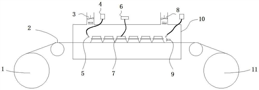
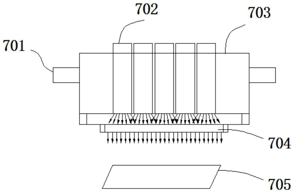
[0045] Such as figure 1 As shown, a pole piece coating drying device includes: an unwinding mechanism 1, used for unwinding the pole piece material roll; a pulley 2, used for transmitting the pole piece material roll at a uniform speed; an air outlet 3, used for discharging The gas keeps the air pressure balance in a dry environment; the data acquisition instrument 4 is used to collect the temperature data obtained by the infrared thermometer 5; the infrared thermometer 5 is used to measure the temperature on the surface of the pole piece material coil and detect the temperature change of the working surface; the power supply The module 6 is used to control the output power of the laser; the laser light source system 7 is used to output the laser of the specified wavelength; the air inlet 8 is used to input the dry gas without moisture to keep the environment clean; the blowing device 9 is used to make the volatilization The solvent moves along the airflow direction (opposite ...


PUM


Abstract

The invention discloses a pole piece coating drying device. The device comprises a pole piece conveying mechanism, an isolation hood and a laser light source system, wherein the pole piece conveying mechanism is used for enabling a pole piece material roll subjected to coating to continuously pass through a laser drying area, the isolation hood is used for relatively isolating the laser drying area from an external environment, the laser light source system is arranged in the isolation hood, is used for outputting laser to dry the pole piece material roll and comprises a plurality of laser modules, each laser module comprises a plurality of laser units arranged in a width direction of the pole piece material roll, each laser module generates small-area light spots, widths of which are not less than a width of the pole piece material roll, and the plurality of laser modules are arranged in a length direction of the pole piece material roll, so that the small-area light spots generated by the plurality of laser modules are spliced into large-area light spots in the length direction of the pole piece material roll. The invention further discloses a pole piece coating drying method. According to the device and the method, uniform drying can be achieved on the whole assembly line, the drying forming efficiency of a pole piece coating is high, and the quality is good.

Description

technical field [0001] The invention relates to the field of production and manufacture of lithium ion batteries, in particular to a pole piece coating drying device and a drying method. Background technique [0002] The production of pole pieces is the basis for the formation of lithium-ion batteries. The control of dust particles and moisture is the most critical control point in the production process. The dust particles are mainly solved by the environmental control in the production line, which is equipped with a dust removal device; and the moisture is mainly Controlled by the drying line, in order to match the high production rate, the length of the lengthy drying line can reach about 15 meters, and the equipment is large in size and takes up a lot of space. Whether it is energy loss or space occupation, it is a huge cost expenditure. [0003] CN201611228865.9 discloses a drying method for electrodes, and mentions the scheme of laser drying pole pieces, but laser dryi...

Claims


Application Information

Patent Timeline
Patent Type & Authority Applications(China)
IPC IPC(8): B05D3/06
CPCB05D3/06
Inventor 李俭国赵敏李志斌黄学杰张春杰
Owner INST OF IND TECH GUANGZHOU & CHINESE ACADEMY OF SCI
Learn More