Programmable serializer for a video display

a serializer and video display technology, applied in the direction of code conversion, computations using pulse rate multipliers/dividers, instruments, etc., can solve the problem of limited display resolution

Active Publication Date: 2008-05-13
TEXAS INSTR INC
View PDF8 Cites 11 Cited by
  • Summary
  • Abstract
  • Description
  • Claims
  • Application Information

AI Technical Summary

Problems solved by technology

This limitation means, in turn, that the resolution of the display is limited by the output data rate of the serializer.

Method used


Image

  • Programmable serializer for a video display
  • Programmable serializer for a video display
  • Programmable serializer for a video display

Examples


Embodiment Construction

[0013]The following discussion is directed to various embodiments of the invention. Although one or more of these embodiments may be preferred, the embodiments disclosed should not be interpreted, or otherwise used, as limiting the scope of the disclosure, including the claims, unless otherwise specified. In addition, one skilled in the art will understand that the following description has broad application, and the discussion of any embodiment is meant only to be exemplary of that embodiment, and not intended to intimate that the scope of the disclosure, including the claims, is limited to that embodiment.

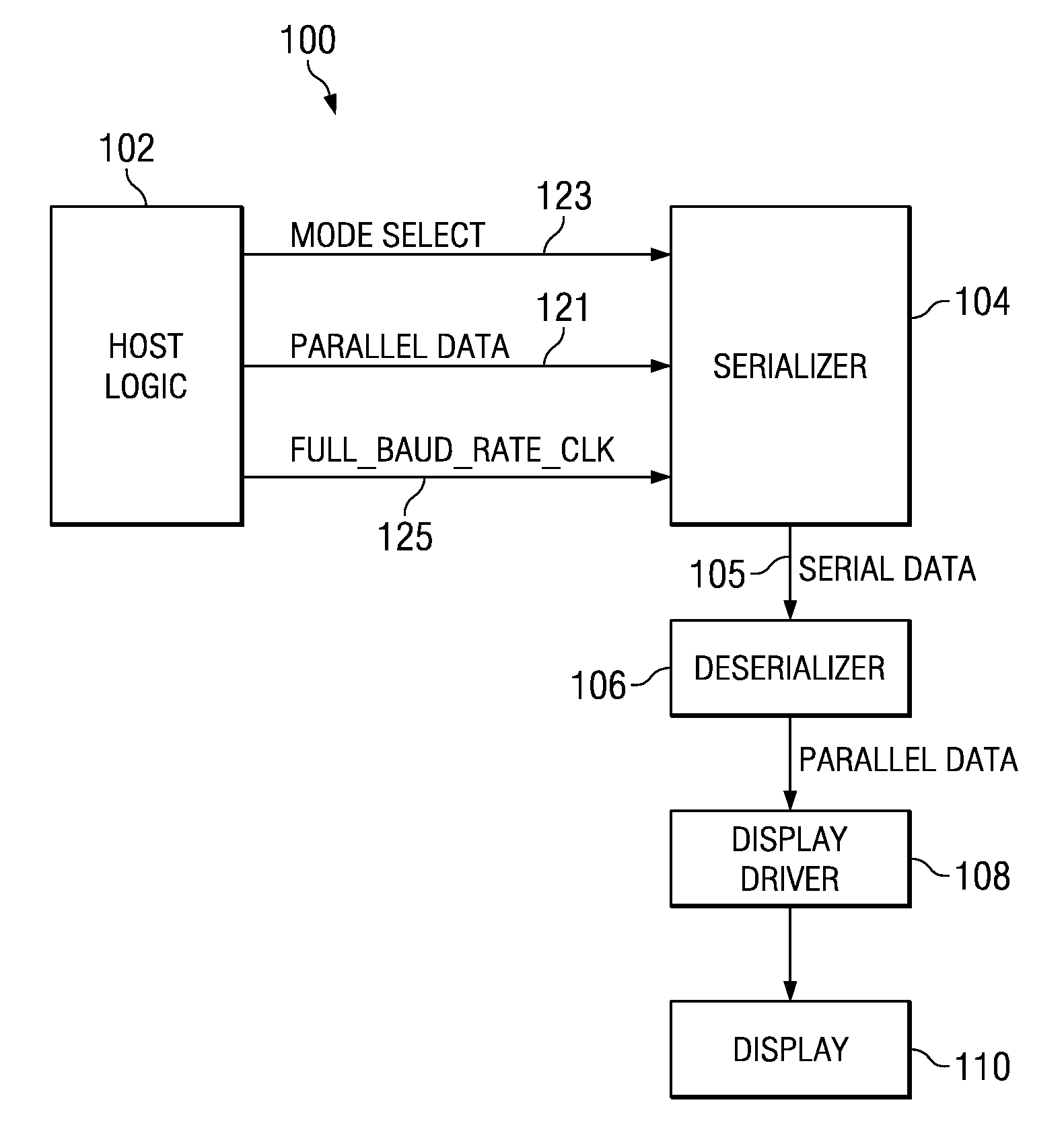
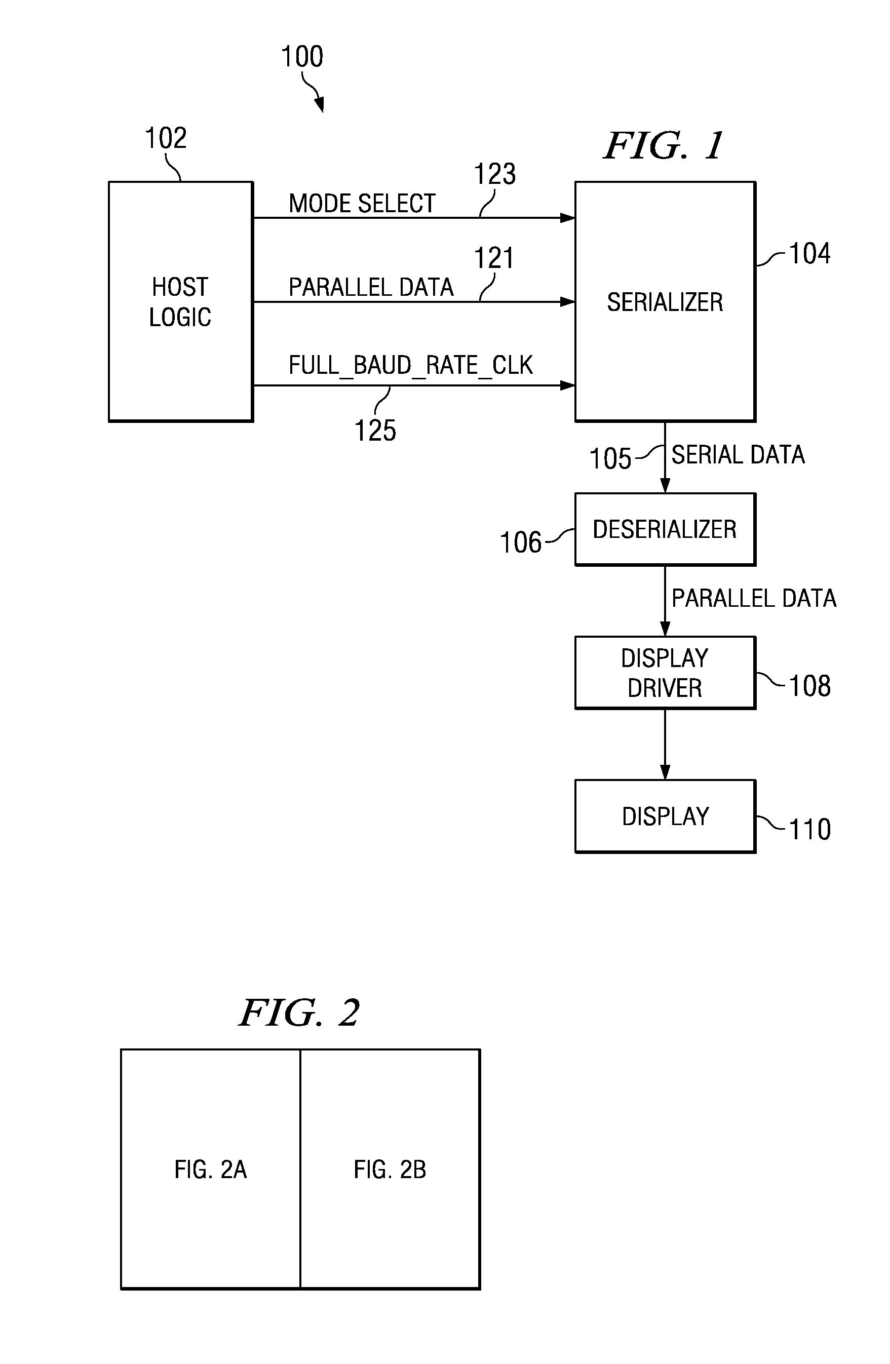
[0014]FIG. 1 shows a preferred embodiment of a system 100 in accordance with a preferred embodiment of the invention. As shown, system 100 comprises host logic 102, a serializer 104, a deserializer 106, a display driver 108, and a display 110. The host logic 102 comprise a processor or source of video data to be shown on the display 110. The serializer 104 receives parallel video...


PUM


Abstract

A serializer receives parallel data and a control signal. The serializer splits the parallel data into multiple subportions of data and, based on the control signal, sequentially outputs each of said subportions as serial output data in one or more serial output channels. The number of serial output channels is dictated by the control signal.

Description

CROSS REFERENCE TO RELATED APPLICATION[0001]This application claims priority to provisional patent application Ser. No. 60 / 695,982, filed Jul. 1, 2005 and incorporated herein by reference.BACKGROUND OF THE INVENTION[0002]1. Technical Field[0003]The present disclosure relates generally to a serializer for producing serial data. More particularly, the present disclosure relates to a programmable serializer for producing serial data for a video display.[0004]2. Background Information[0005]In some situations, video data is converted from a parallel format to a serial format. A serializer is a device that converts such parallel data to serial data. An application of a serializer is for a cellular telephone in which the logic (e.g., a processor) that generates the video data and the display on which the video data is provided are provided in two separate parts of the telephone separated by a hinge. That is, the processor is in the main part of the phone and the display is provided in a co...

Claims


Application Information

Patent Timeline
Patent Type & Authority Patents(United States)
IPC IPC(8): H03M9/00
CPCG09G5/006G06F7/68G09G3/2096G09G2370/045
Inventor CHAN, CHUNG S R
Owner TEXAS INSTR INC
Why Eureka
Try Eureka