Camera with video capturing button and still capturing button capable of simultaneous operation

Inactive Publication Date: 2008-05-13
FUJIFILM CORP +1
View PDF3 Cites 57 Cited by
  • Summary
  • Abstract
  • Description
  • Claims
  • Application Information

AI Technical Summary

Benefits of technology

[0017]This arrangement ensures that still picture data can be recorded on another recording medium without causing a discontinuity in moving picture data.
[0018]According to the present invention, as described above, in a camera having

Problems solved by technology

With the conventional camera having both of two picture-taking buttons provided in a rear (or side) surface, however, there is a problem described below.
There is a possibility of picture taking being performed differently from one's intention by such an erroneous operation.
The possibility of such an erroneous operation is high in the case of use of a camera having a moving-picture-taking button and a still-picture-taking button placed close to each other in a miniaturization design.
Even in a case where an operator depresses a pictur

Method used


Image

  • Camera with video capturing button and still capturing button capable of simultaneous operation
  • Camera with video capturing button and still capturing button capable of simultaneous operation
  • Camera with video capturing button and still capturing button capable of simultaneous operation

Examples


first embodiment

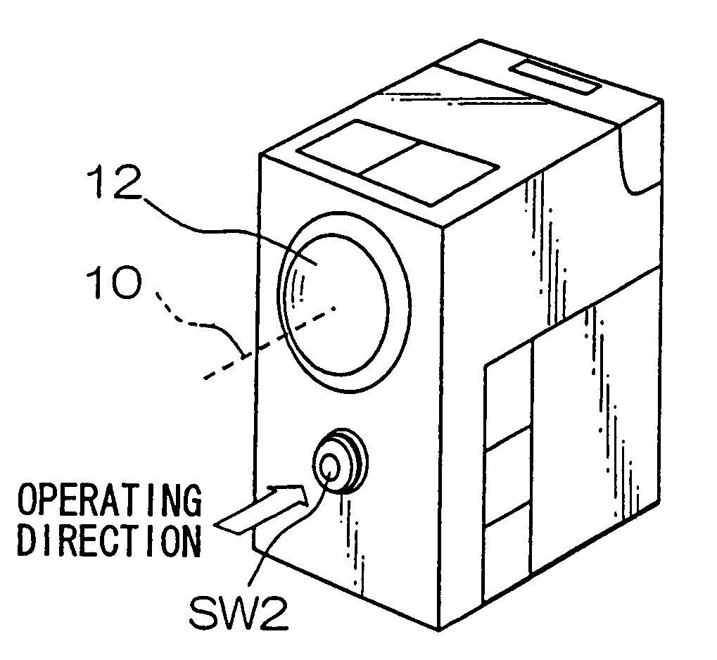
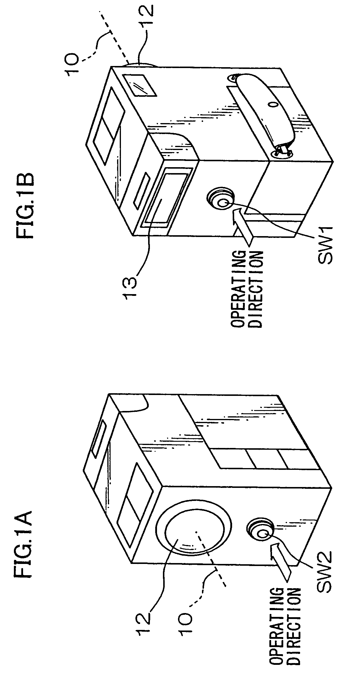
[0028]FIG. 1A is a front perspective view of a camera which represents a first embodiment of the present invention, and FIG. 1B is a rear perspective view of the camera.

[0029]A moving-picture-taking button SW1, which is a button depressed at the time of moving picture taking, is provided in a rear surface of a camera body so that the operating direction (the direction in which the button is depressed) is parallel to an optical axis 10 of a picture-taking lens 12. When an operator holds the camera with the picture-taking lens 12 directed toward a subject, the moving-picture-taking button SW1 faces in a direction toward the operator (opposite from the picture-taking direction) and is depressed in a direction toward the subject (picture-taking direction) by the operator. In this embodiment, the moving-picture-taking button SW1 is changed from an off state to an on state when depressed one time and is changed from the on state to the off state when again depressed.

[0030]A still-picture-...

second embodiment

[0043]FIG. 4A is a front perspective view of a camera which represents a second embodiment of the present invention, and FIG. 4B is a rear perspective view of the camera. FIG. 5 is a block diagram showing essential portions of the internal configuration of the camera. The same portions as those in the first embodiment shown in FIGS. 1 and 2 are indicated by the same reference characters.

[0044]In the camera of this embodiment, a plurality of recording mediums 20a and 20b can be detachably attached to the camera independently of each other. More specifically, each of recording mediums 20a and 20b can be removed from the camera after opening a cover 14, as shown in FIG. 4B.

[0045]Description will be made by assuming that each of the first recording medium 20a and the second recording medium 20b is a memory card, moving picture data is recorded on the first recording medium 20a, and still picture data is recorded on the second recording medium 20b. In actuality, mediums different from ea...


PUM


Abstract

One of first and second picture-taking operating devices is placed in a rear surface of a camera body, while the other of the picture-taking operating devices is placed in a front surface of the camera body. An operator can selectively use the two picture-taking operating devices and can therefore be prevented from erroneously operating the operating devices. Each of the picture-taking operating devices is provided so that its operating direction is parallel to the optical axis of a picture-taking lens. Therefore, camera shake due to an operating force can be reduced. When the first picture-taking operating device is operated, picture data on a subject is recorded on a first recording medium. When the second picture-taking operating device is operated, picture data on the same subject is recorded on a second recording medium. The two picture-taking operating devices are selectively used to distribute picture data to the corresponding recording mediums.

Description

BACKGROUND OF THE INVENTION[0001]1. Field of the Invention[0002]The present invention relates to a camera and, more particularly, to a camera having a plurality of picture-taking operating devices operated to input instructions to perform different picture-taking operations.[0003]2. Description of the Related Art[0004]In conventional cameras having a moving-picture-taking button depressed to take a moving picture and a still-picture-taking button depressed to take a still picture, each of these picture-taking buttons is ordinarily provided in a rear surface which faces an operator holding the camera during picture taking or in a side surface to be depressed sideways by the right or left hand of an operator holding the camera during picture taking.[0005]A camera has also been proposed which has a picture-taking button for vertical-position picture taking to be depressed when the camera is vertically held and a picture-taking button for horizontal-position picture taking to be depress...

Claims


Application Information

Patent Timeline
IPC IPC(8): H04N5/225G03B17/38G03B1/00H04N5/232
CPCH04N5/232H04N23/51
Inventor FUJIMURA, YUICHI
Owner FUJIFILM CORP
Why Eureka
Try Eureka