Method and system for visualizing surface errors

Active Publication Date: 2008-05-13
FARO TECH INC
View PDF24 Cites 131 Cited by
  • Summary
  • Abstract
  • Description
  • Claims
  • Application Information

AI Technical Summary

Benefits of technology

[0013]Another object of the invention is to reduce the time required to rework a surface, particularly

Problems solved by technology

Conventional CMM's have limited usage in large scale manufacturing, for example, in aerospace or boat building industries.
It is suitable for automated surface measurement, but this system is very expensive.
Some of parts and, especially, large tools in aerospace industry are so expensive in production that it is often more reasonable to manually rework and correct their surface flaws rather to completely remake them.
However, for the surface rework process it is not enough to see detected imperfections on a computer screen but it is absolutely necessary to map and locate those imperfe

Method used


Image

  • Method and system for visualizing surface errors
  • Method and system for visualizing surface errors
  • Method and system for visualizing surface errors

Examples


Embodiment Construction

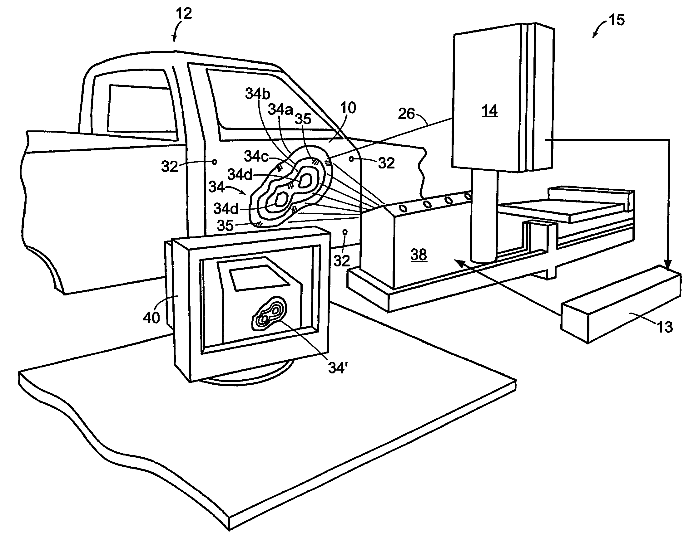
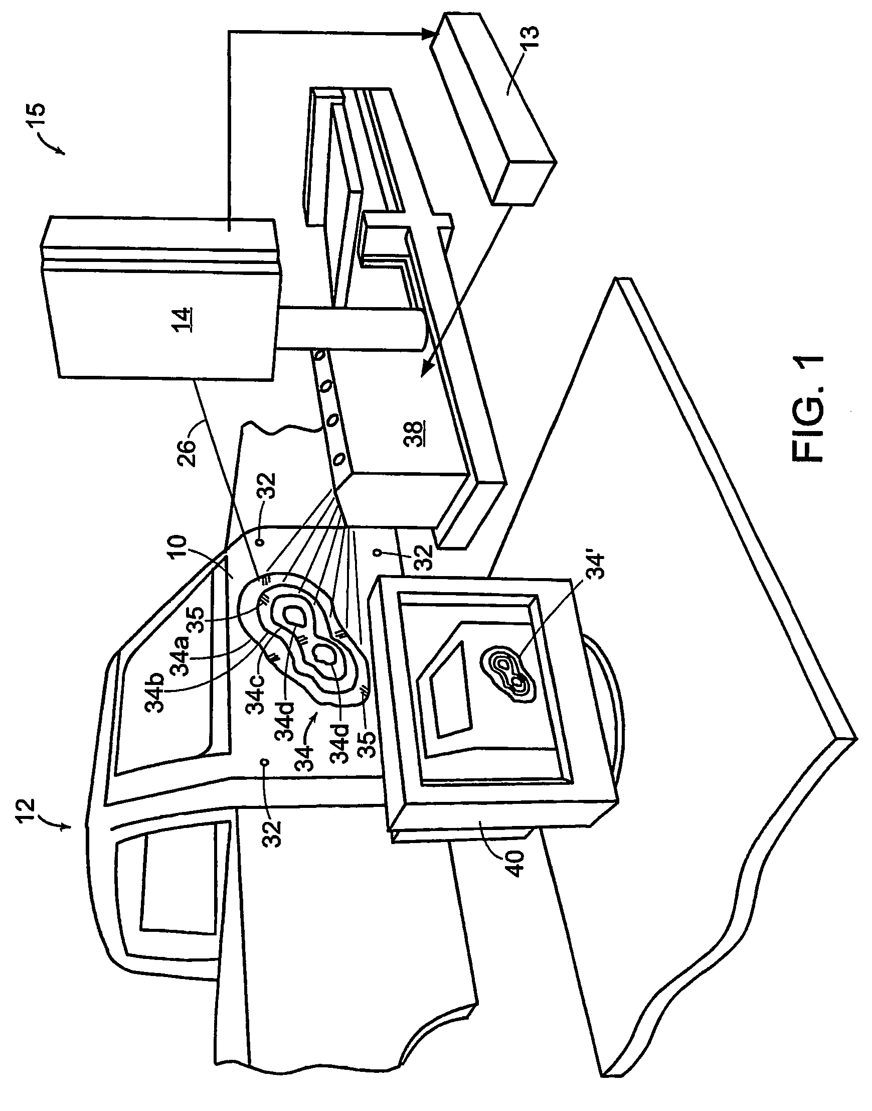
[0031]With reference to FIGS. 1 and 2, the present invention is a system 15 and method for visualizing errors on a surface 10 shown in FIG. 1 by way of an example as an exterior panel of a door of a pickup truck 12. The major components of the visualization system 15 are a laser tracker 14 that measures actual shape of the surface 10, a processor 13, and an optical projector 38 that displays a visual topographical error pattern 34 on the surface 10.

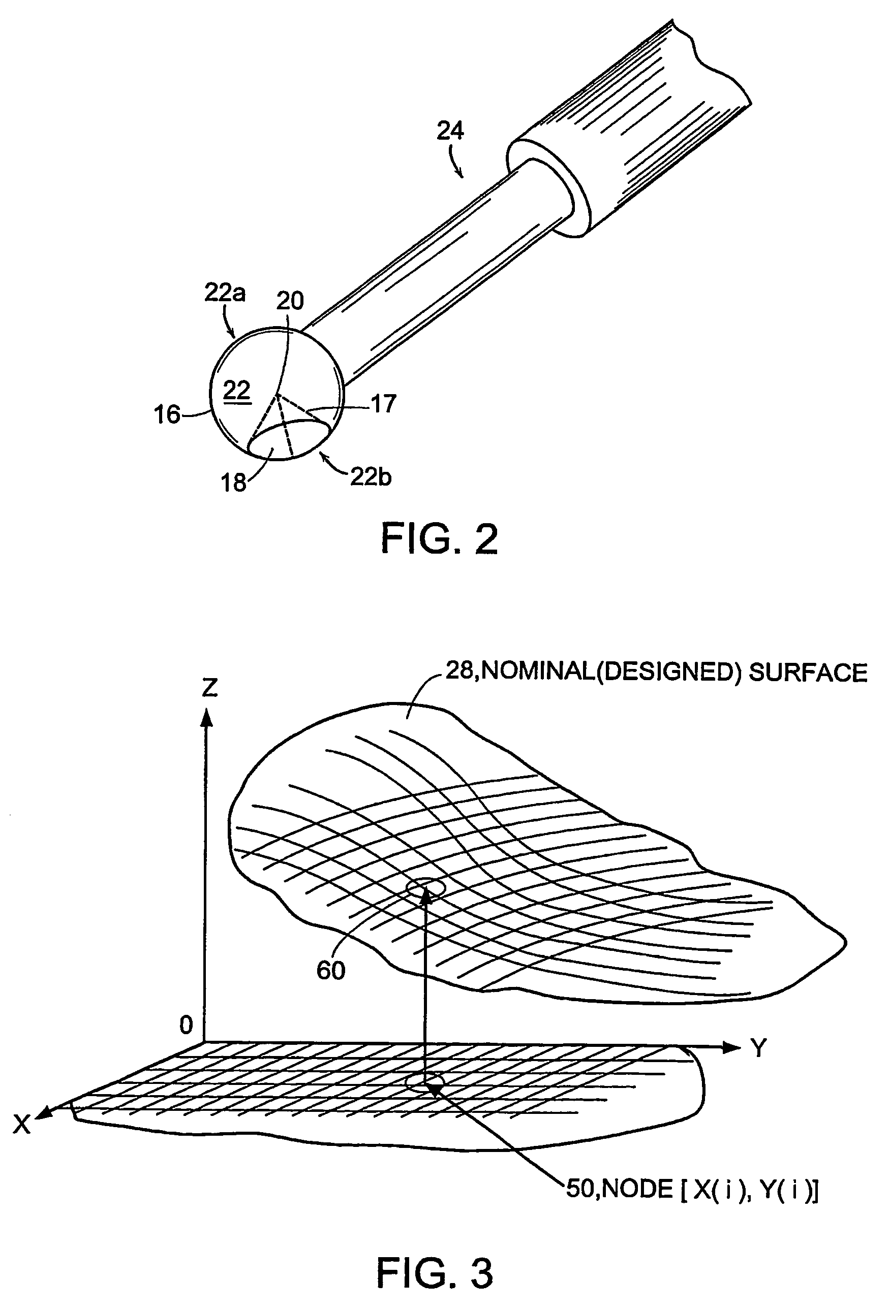
[0032]Laser tracker 14 provides surface profile measurements. It is being operated in conjunction with a retro-reflective element 16 (FIG. 2) that can be moved freely over the surface 10. The retro-reflective element 16 has a high precision comer cube prism 17 mounted inside a hardened steel ball 22. A front face 18 of the comer cube prism 17 opens outwardly through the circular cut 22b in the ball 22. A vertex 20 of the prism 17 is precisely aligned with the geometric center of the ball 22. A hand-held wand 24 carries the ball at one end...


PUM


Abstract

A method and system for visualizing deviations on an actual surface 10, 30 from a nominal, or designed, surface 28 utilizes a system and method for mapping the spatial (e.g. x, y and z) coordinates of the actual surface 10, 30 into a computer 13, comparing the mapped actual surface to the nominal surface 28 to produce a three-dimensional distribution of deviation values (D), processing this distribution into a topographical pattern 34 of multiple contours or areas 34a . . . 34n, each contour or area having the same, or generally the same, deviation value (D), and optically projecting this topographical pattern 34 onto the actual surface 10, 30 in registry with the initial surface mapping to provide a display of the surface deviations (D) directly on the actual surface 10, 30. The deviations are measured along a direction D normal to the actual surface so that the three-dimensional distribution is given in x, y, D coordinates. The optical projection is preferably a laser projection 38. The mapping and projection onto the actual surface 10, 30 are made, and coordinated with one another, with respect to three reference points 32 on the surface 10, 30.

Description

CROSS REFERENCE TO RELATED APPLICATIONS[0001]This application is a Section 371 filing of PCT / US02 / 32520 filed 11 Oct. 2002 which claims priority under 35 USC 119(e) of U.S. provisional application No. 60 / 328,685 filed 11 Oct. 2001.BACKGROUND OF THE INVENTION[0002]This invention relates in general to surface verification and correction in the process of manufacturing, and more specifically, to a method and system for producing an optical, topographical display of surface profile errors directly on the surface.[0003]In the process of manufacturing a large part, such as a tool, a mold, or a stamped sheet metal panel where it is important that the surface be precisely shaped, e.g. as in the aerospace industry, it is usually required to verify and, if necessary, to accurately correct (rework) the shape of the surface. Obviously, the surface shape has to be compared with design specifications. In modern production, parts, tools, dies, and molds are usually designed based on computer-assis...

Claims


Application Information

Patent Timeline
IPC IPC(8): G01N21/00G01B11/24G01B11/25G03B31/00G06K9/00
CPCG01B11/2513G03B31/00
Inventor KAUFMAN, STEVEN P.SAVIKOVSKY, ARKADY
Owner FARO TECH INC
Why Eureka
Try Eureka