Flame simulating assembly

a technology of assembly and flame, applied in the field of flame simulating assembly, can solve the problems of reducing the simulation effect, affecting the simulation effect,

Inactive Publication Date: 2008-05-20
GLEN DIMPLEX AMERICAS LTD
View PDF161 Cites 45 Cited by
  • Summary
  • Abstract
  • Description
  • Claims
  • Application Information

AI Technical Summary

Benefits of technology

[0011]In yet another aspect, the exposed surface additionally includes one or more covered portions for simulating the dark portion of the actual fuel element.
[0012]In another of its aspects, the invention provides a method of forming a simulated fuel element for simulating an actual fuel element in a fire. The method includes, first, the step of providing a light-transmitting body with a base surface on which the body is positionable when the body is disposed in a predetermined position, and an untreated surface which is substantially exposed when the body is in the predetermined position. Next, the untreated surface is at least partially covered with a treatment material, to provide a preliminary exposed surface. Finally, one or more uncovered portions of the preliminary exposed surface are formed, to permit light to be transmitted through the uncovered portion(s) so that the uncovered portion(s) simulate the glowing portion(s) of the actual fuel element.
[0013]In yet another aspect, the step of forming the uncovered portions at least partially defines one or more covered portions for simulating the dark portion(s) of the actual fuel element.
[0014]In yet another of its aspects, the invention provides another method of forming a simulated fuel element for simulating an actual fuel element in a fire. The method includes, first, the step of providing a light-transmitting body with a base surface on which the body is positionable when the body is disposed in a predetermined position. The body also includes an untreated surface which is substantially exposed when the body is in the predetermined position. Next, one or more light-transmitting portions of the base surface are masked to substantially prevent a treatment material from contacting the light-transmitting portion. In the next step, the untreated surface is at least partially covered with the treatment material, to provide a preliminary exposed surface. Finally, one or more uncovered portions of the preliminary exposed surface are formed to permit light to be transmitted through the uncovered portion(s) so that the uncovered portion(s) simulates the glowing portion(s) of the actual fuel element.
[0015]In another of its aspects, the invention provides a simulated fuel bed for simulating an actual fuel bed including one or more actual fuel elements having one or more glowing portions and one or more dark portions. The simulated fuel bed includes one or more light sources, a simulated ember bed, and one or more simulated fuel elements. The simulated ember bed is positioned in a path of light from the light source and is adapted for transmission of light from the light source therethrough. The simulated fuel element is positioned on an upper surface of the simulated fuel bed, and includes a base surface which is positioned proximal to the upper surface. The base surface includes one or more light-transmitting portions through which the light from the light source is transmittable. The simulated fuel element also includes an exposed surface which is at least partially viewable and which includes one or more uncovered portions through which light from the light source is transmittable. Accordingly, light from the light source is transmittable through the simulated ember bed and through the uncovered portion(s) to simulate the glowing portion(s) of the actual fuel element.
[0016]In yet another aspect, each simulated fuel element's exposed surface includes one or more covered portions (which are covered with the treatment material) for simulating the dark portion(s) of the actual fuel element.

Problems solved by technology

However, the use of a partially translucent shell such as the cover disclosed in Dewey to imitate burning solid combustible fuel has some disadvantages.
Because it is evident from even a cursory observation of this type of prior art imitative fuel bed that the raised parts (i.e., simulated logs) are formed integrally with the simulated ember bed part of the shell, this type of imitative fuel bed tends to detract from the simulation effect sought.
However, the known imitative coal pieces have some disadvantages.
Also, the part of the surface of each prior art imitative coal piece which is not glowing tends to be much more glossy than the surfaces of coal pieces in a real fire, so that the simulation provided is thereby undermined.

Method used


Image

  • Flame simulating assembly
  • Flame simulating assembly
  • Flame simulating assembly

Examples


Embodiment Construction

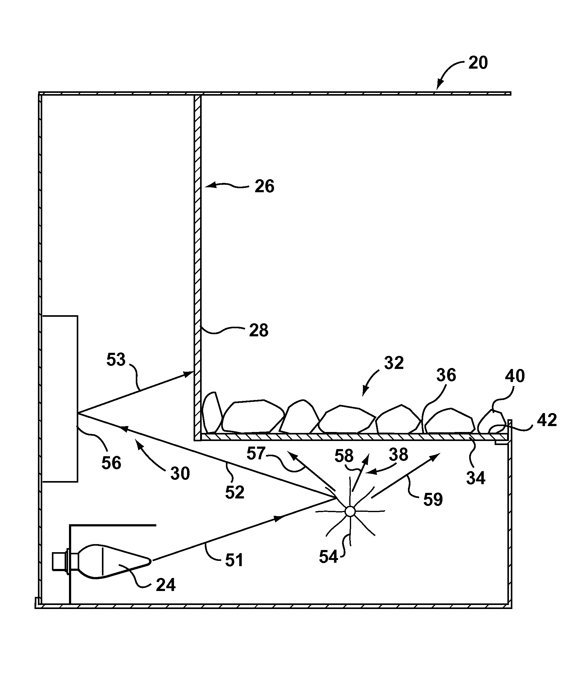
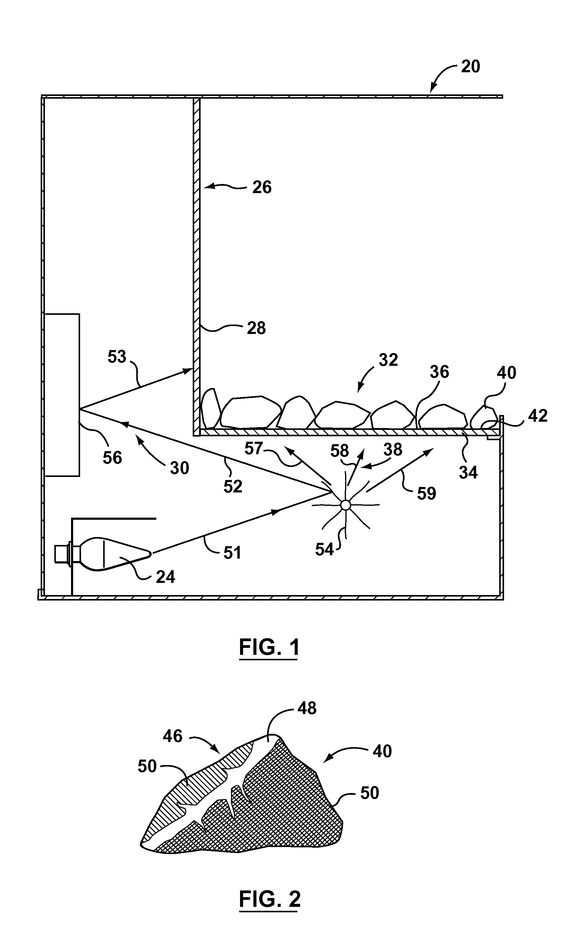
[0024]Reference is first made to FIGS. 1-4 to describe an embodiment of a flame simulating assembly in accordance with the invention indicated generally by the numeral 20. The flame simulating assembly 20 is for providing one or more images of flames 22 and simulating an actual fuel element in a fire (not shown) having one or more glowing portions and one or more dark portions. The flame simulating assembly 20 includes one or more light sources 24 and a screen 26 having a front surface 28. The screen 26 is positioned in a first path of light 30 (FIG. 1) from the light source 24. Preferably, the screen 26 is adapted for transmission of the image of flames 22 therethrough, as will be described. The flame simulating assembly 20 also preferably includes a simulated fuel bed 32 positioned at least partially in front of the front surface 28. It is preferred that the simulated fuel bed 32 includes a simulated ember bed 34 with an upper surface 36 (FIG. 1). Preferably, the simulated ember b...


PUM


Abstract

A flame simulating assembly for providing an image of flames and simulating one or more actual fuel elements in a fire. The flame simulating assembly includes one or more light sources, a screen adapted for transmission of the image of flames therethrough, and a simulated fuel bed. The simulated fuel bed includes a simulated ember bed and one or more simulated fuel elements positioned on an upper surface of the simulated ember bed. Each simulated fuel element includes a base surface with a light-transmitting portion and an exposed surface which is at least partially viewable. The base surface is positioned proximal to the upper surface of the simulated ember bed. The exposed surface includes one or more uncovered portions through which light from the light source is transmittable.

Description

FIELD OF THE INVENTION[0001]The present invention relates to flame simulating assemblies.BACKGROUND OF THE INVENTION[0002]Various types of flame simulating assemblies, such as electric fireplaces, are known. Many of the prior art flame simulating assemblies include one or more components intended to resemble actual fuel in a real fire. Typically, the fuel which is simulated is wood (i.e., logs), or coal.[0003]For example, U.S. Pat. No. 566,564 (Dewey) discloses an electric heating apparatus with a cover (B′) which “is made . . . of a transparent or semitransparent material” (p. 1, lines 50-52). The cover is “fashioned or colored” so that it resembles coal or wood “in a state of combustion when light is radiated through it” (p. 1, lines 53-57).[0004]However, the use of a partially translucent shell such as the cover disclosed in Dewey to imitate burning solid combustible fuel has some disadvantages. In particular, a portion of the shell typically is formed to simulate the fuel (e.g.,...

Claims


Application Information

Patent Timeline
Patent Type & Authority Patents(United States)
IPC IPC(8): G09F19/12
CPCF24C7/004F21S10/04Y10S362/806
Inventor HESS, KRISTOFFER
Owner GLEN DIMPLEX AMERICAS LTD
Why Eureka
Try Eureka