Vehicle roof having openable roof parts

a technology of roof parts and vehicles, applied in the field of vehicles, can solve the problems of complex kinematic mechanisms and achieve the effect of preventing the unplanned lowering motion of the rear roof parts

Inactive Publication Date: 2008-05-20
MAGNA CAR TOP SYST GMBH
View PDF8 Cites 2 Cited by
  • Summary
  • Abstract
  • Description
  • Claims
  • Application Information

AI Technical Summary

Benefits of technology

[0007]An object of the present invention is to provide by a vehicle roof having front and rear openable roof parts in a roof opening in which the roof parts are stably mounted when the roof is in the closed position and undesired lowering motion of the rear roof part is prevented.
[0011]A kinematic support mechanism fixes the rear roof part in place with the roof is in the closed position. The kinematic support mechanism supports the rear roof part in the closed position, thereby reliably preventing an undesired or unintentional lowering motion of the rear roof part when the roof is closed. As such, the kinematic support mechanism acts upon the rear roof part.
[0012]The front roof part acts upon the kinematic support mechanism in a direction of a support position of the kinematic support mechanism thereby preventing the kinematic support mechanism from inadvertently giving way and thus prevent the rear roof part from lowering even when relatively large forces act on the rear roof part.
[0013]In the closed position, the kinematic support mechanism fixes the height of the rear roof part and is locked in place by the front roof part. In this manner, the height of the rear roof part can be fixed by the adjusting motion of the front roof part. The front roof part advantageously achieves the transfer of the kinematic support mechanism to the support position as well as maintenance of the kinematic support mechanism in the support position. In this manner, a relatively simple design for the kinematic support mechanism is sufficient for providing effective support when the roof is in the closed position. No complicated coupling kinematic system is required for a motion coupling between the roof parts such that conventional kinematic mechanisms may achieve the adjusting motion of the roof parts.
[0014]In an embodiment of the present invention, the front roof part which triggers the support function is longitudinally displaceable along the plane of the fixed outer roof skin and is not upwardly or downwardly displaceable like the rear roof part. The front roof part is guided in lateral guides bordering the longitudinal extending sides of the roof opening at the level of the fixed outer roof skin. To open the roof, the rear roof part is lowered thereby enabling the front roof part to be slid horizontally above the rear roof part. Optionally, the rear roof part may undergo an additional displacement motion thus allowing an overall larger roof opening to be exposed.

Problems solved by technology

However, a complex kinematic mechanism is necessary for this purpose.

Method used


Image

  • Vehicle roof having openable roof parts
  • Vehicle roof having openable roof parts
  • Vehicle roof having openable roof parts

Examples


Embodiment Construction

)

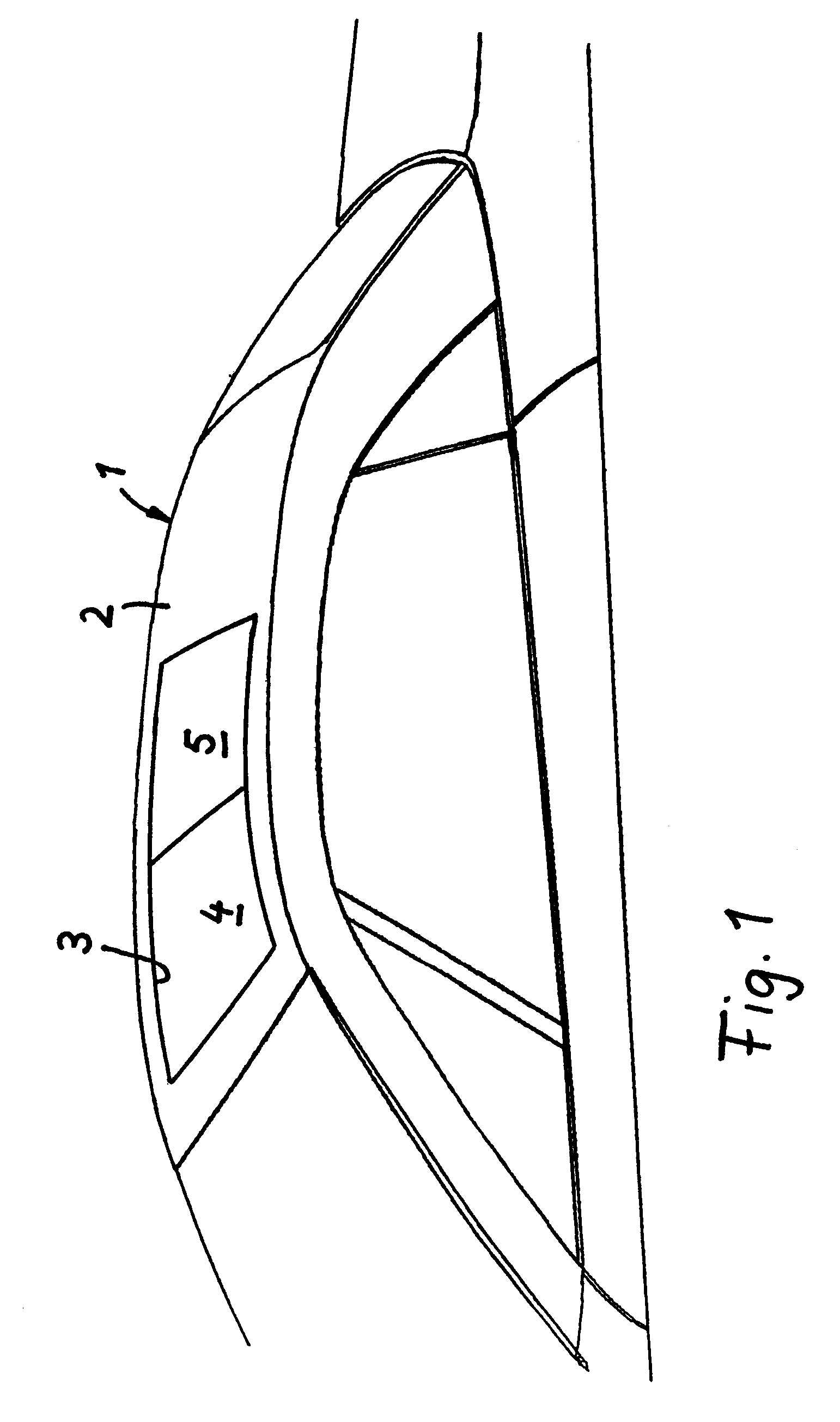
[0025]Referring now to FIG. 1, a perspective view of a vehicle roof 1 having front and rear openable roof parts 4, 5 situated within a common roof opening 3 of a fixed outer roof skin 2 in accordance with an embodiment of the present invention is shown. Roof 1 has a solid design and is fixedly connected to a motor vehicle body. In a closed position of roof 1 (shown in FIG. 1), roof parts 4, 5 are arranged flush behind one another within roof opening 3 to thereby close off roof opening 3. Roof parts 4, 5 lie one behind one another as viewed in the longitudinal direction of the vehicle in the closed position. Particularly, in the closed position, the rear edge of front roof part 4 borders the front edge of rear roof part 5, while the front edge of front roof part 4, the rear edge of rear roof part 5, and the side edges of roof parts 4, 5 lie flush with fixed outer roof skin 2.

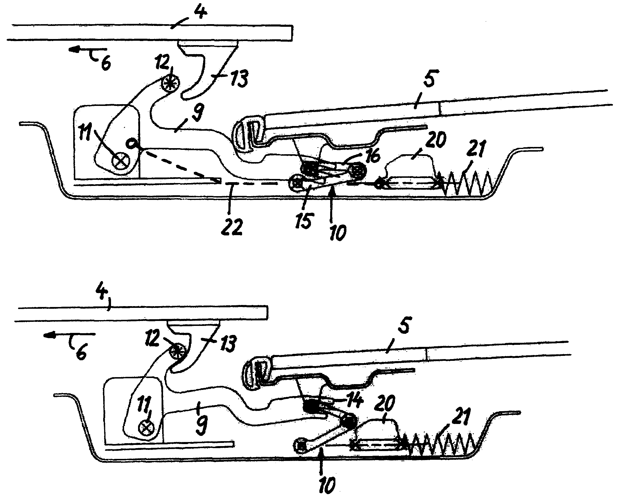
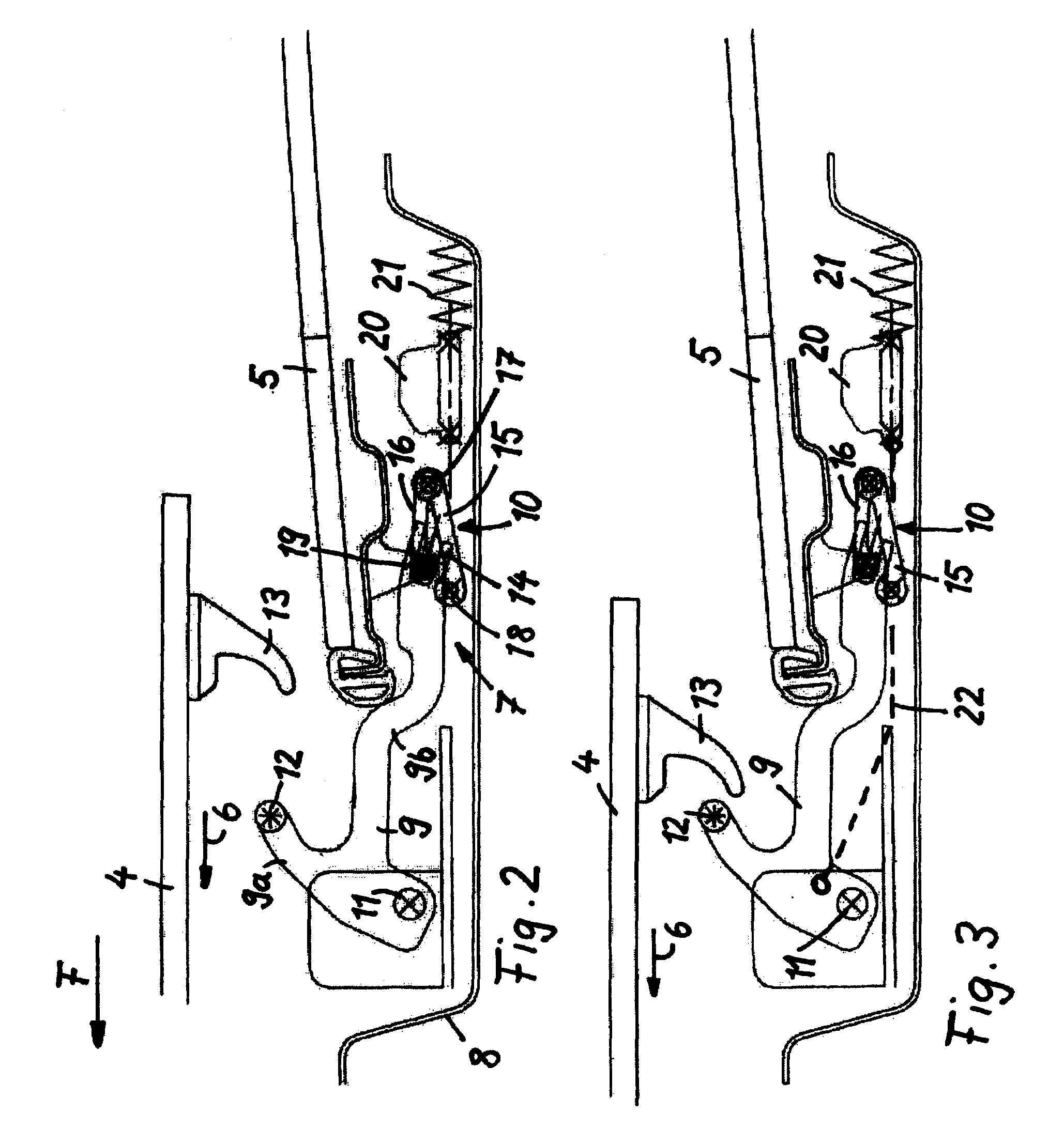
[0026]In an opened position of roof 1, the front edge of rear roof part 5 is lowered with respect to fixed ou...


PUM


Abstract

A vehicle roof includes a roof opening in a roof skin. First and second roof parts are movable between a closed position in which the parts are arranged flush behind one another within the roof opening to thereby close off the roof opening and in an opened position in which the second part is lowered with respect to the roof skin and the first part extends over the second part to thereby expose the roof opening. A kinematic support mechanism is movable to an extended position in which the mechanism fixes the second part in the closed position and in a retracted position in which the mechanism lowers the second part in the opened position. The first part and the mechanism are connected to one another such that the first part actuates the mechanism between its positions in response to the first part moving between the closed and opened positions.

Description

CROSS-REFERENCE TO RELATED APPLICATIONS[0001]This application claims foreign priority benefits under 35 U.S.C. § 119(a)-(d) to DE 10 2005 047 505.1, filed Oct. 4, 2005, which is hereby incorporated by reference in its entirety.BACKGROUND OF THE INVENTION[0002]1. Field of the Invention[0003]The present invention relates to a vehicle roof having a roof opening within a fixed roof skin in which at least two roof parts are flush behind one another in a closed position which closes off the roof opening and in which the roof parts partially overlap one another in an opened position which exposes the roof opening.[0004]2. Background Art[0005]DE 199 53 104 C1 (corresponds to U.S. Pat. No. 6,416,122) describes a vehicle roof having two roof covers (i.e., roof parts) situated in a common roof opening of a vehicle. The roof parts are adjustable between closed and opened positions. In the closed position, the roof parts are flush one behind the other to cover the roof opening. In the opened pos...

Claims


Application Information

Patent Timeline
Patent Type & Authority Patents(United States)
IPC IPC(8): B60J7/047
CPCB60J7/047B60J7/19
Inventor STRIEGEL, KLAUSKLEIN, BERTHOLDSALZ, WOLFRAMKATRINI, WALERI
Owner MAGNA CAR TOP SYST GMBH
Why Eureka
Try Eureka