
Lighted handle

a technology of lighted handles and handles, applied in the field of handles, can solve the problems of complicated device, extra cost of materials and installation, and difficulty for a person to easily see such a handle,

Inactive Publication Date: 2008-05-20
ITC LIMITED
View PDF21 Cites 15 Cited by
  • Summary
  • Abstract
  • Description
  • Claims
  • Application Information

AI Technical Summary

Benefits of technology

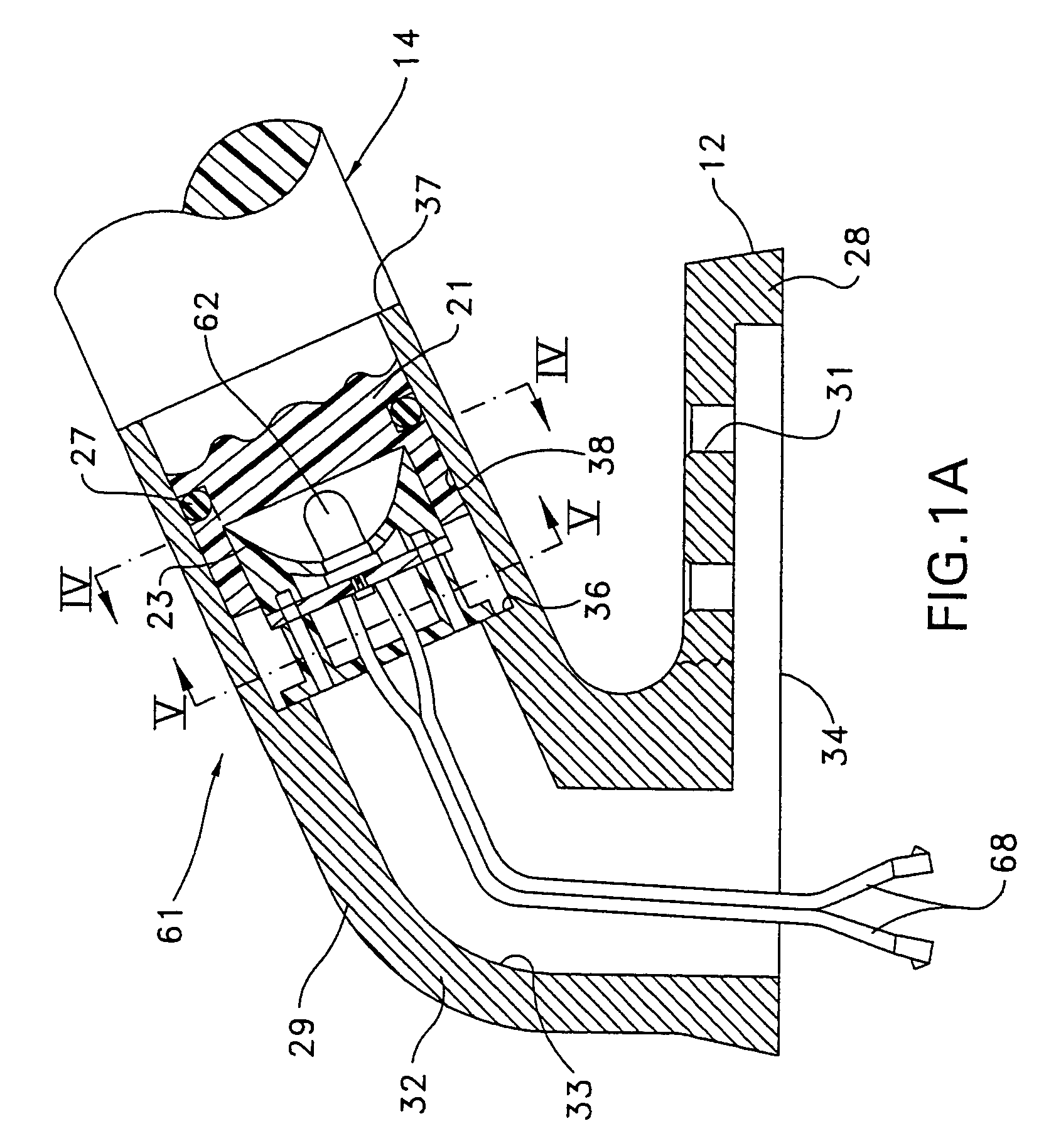
[0007]This invention is directed to a new and useful lighted handle. The lighted handle of this invention includes a light transmitting member having a first end portion, a second end portion and a central portion. A first end bracket carries the first end portion and a second end bracket carries the second end portion. Positioned between the light transmitting member and the first end bracket is a narrow beam light emitter, conveniently a light emitting diode (LED).

Problems solved by technology

However, it is sometimes difficult for a person to easily see such a handle, which can blend in to its surroundings, and / or be hidden by twilight or the darkness of night.
However, such a light source may cause extra expense for materials and installation, and, in the case of the visual incandescent fixture, electric power use.
Thus, the '621 patent disclosed device is complicated by its requirement for a divergent lens 16, as well as a curved mirror, or reflector, 18.

Method used


Image

  • Lighted handle
  • Lighted handle
  • Lighted handle

Examples


Embodiment Construction

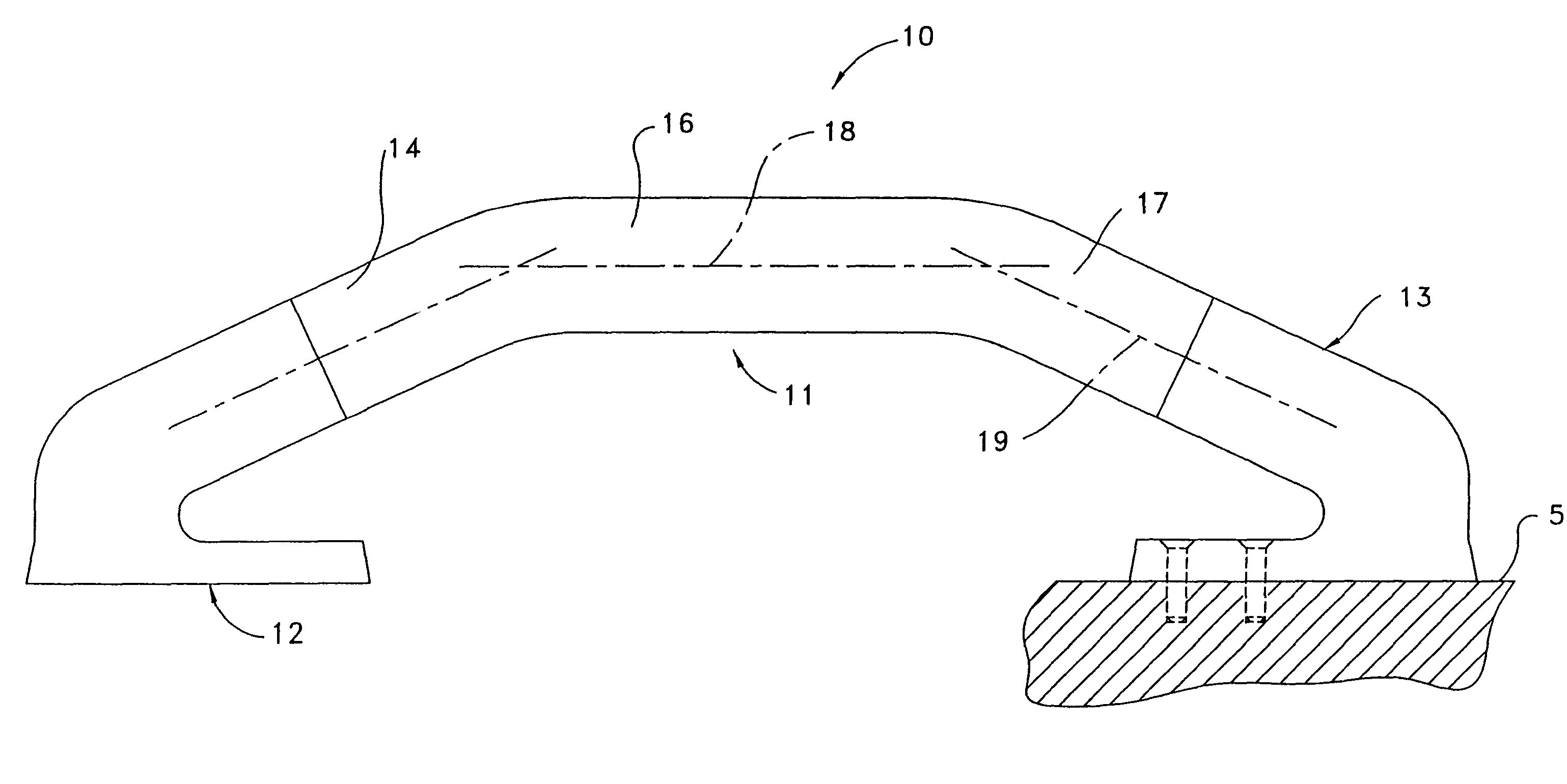
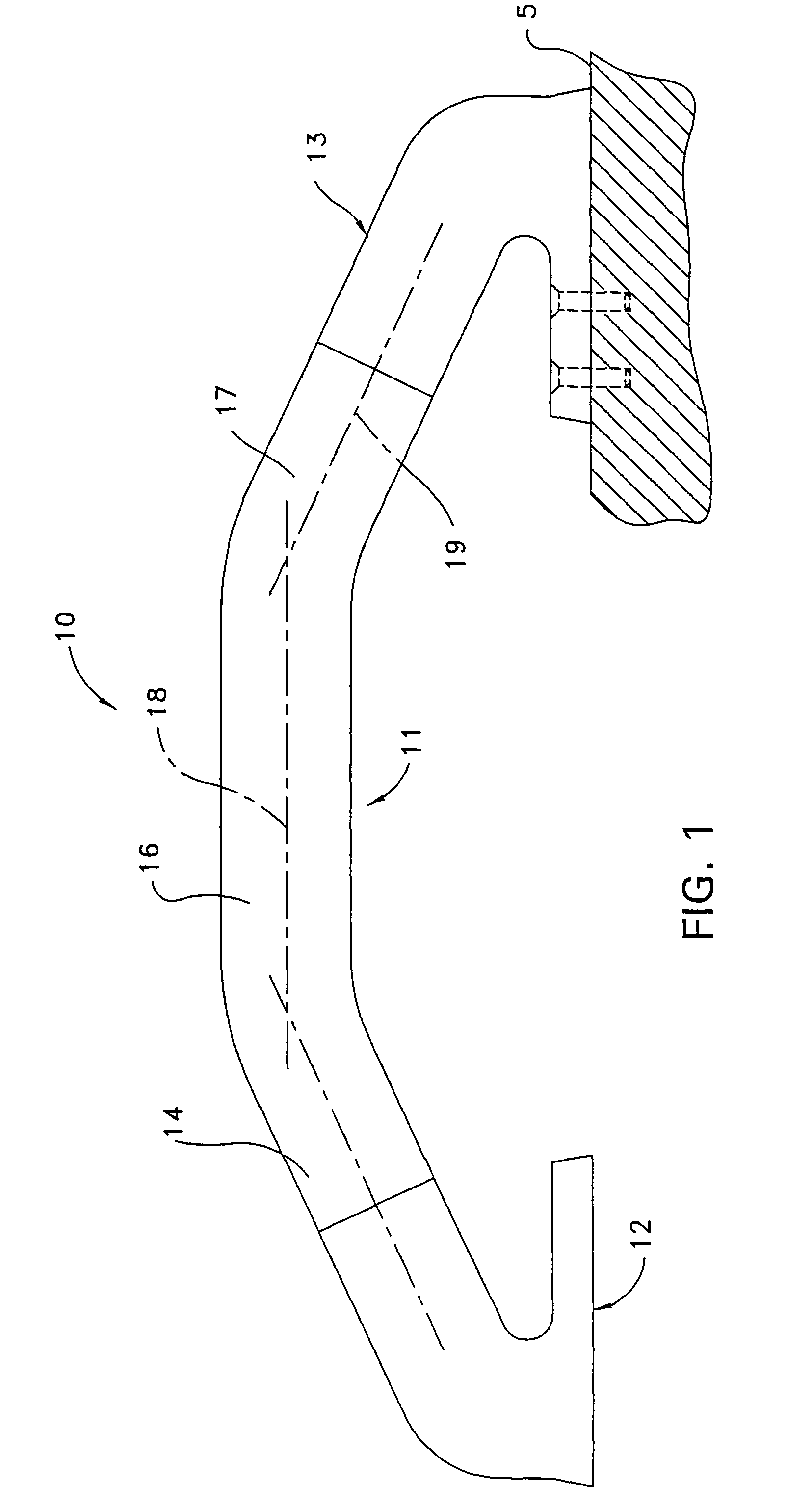
[0048]FIG. 1 shows a lighted handle 10 according to one embodiment of the present invention. The lighted handle 10 includes a light transmitting member 11 that is fixedly carried and flanked by preferably identical end brackets 12 and 13.

[0049]The light transmitting member 11 (FIG. 1) has a first end portion 14 coupled to a second end portion 17 by a central portion 16. The light transmitting member 11 comprises a rigid, preferably transparent and preferably circular cross-section rod of suitable material, preferably an extrudable polymer, such as acrylic. The light transmitting member 11 may be straight or of any desired shape. However, and preferably, the FIG. 1 light transmitting member 11 is bent, such that the first end portion 14 and the second end portion 17 are bent away from a central portion longitudinal axis 18. Preferably, the first end portion 14 and the second end portion 17 are bent at an angle between 20 to 30 degrees, and preferably about 25 degrees, with respect to...


PUM


Abstract

A lighted handle includes an elongate light transmitting member that has first and second end portions. First and second support surface engageable mounting brackets carry the first and second end portions of the light transmitting member. A narrow beam light emitter is located in the first mounting bracket and has a light beam emitting end. The light beam emitting end faces the adjacent first end portion of the light transmitting member and is aimed longitudinally along the light transmitting member to make the same more visible.

Description

[0001]This application is a continuation-in-part of U.S. application Ser. No. 09 / 999,814, filed Oct. 31, 2001 now U.S. Pat. No. 6,592,240FIELD OF THE INVENTION[0002]This invention relates generally to handles.BACKGROUND OF THE INVENTION[0003]Handles have been positioned adjacent steps and along walkways for gripping by and assistance to a person moving therealong. For instance, recreational vehicles and boats have often included such handles. For example, such a handle is often located near a door of a recreational vehicle on the outside wall to aid a person stepping up into, or down from such a vehicle. In addition, such a handle may be located near the cockpit-to-cabin steps and / or along walkways in a boat to steady a person against boat movement in a seaway.[0004]However, it is sometimes difficult for a person to easily see such a handle, which can blend in to its surroundings, and / or be hidden by twilight or the darkness of night. Such a handle can be made more visible by illumi...

Claims


Application Information

Patent Timeline
Patent Type & Authority Patents(United States)
IPC IPC(8): F21V21/08A47K3/00B60Q1/26E04F11/18F21S4/00F21V8/00
CPCA47K3/003B60Q1/2669B60Q3/004B60Q3/0233E04F11/1804E05B17/10F21S4/008G02B6/0006G02B6/001E04F2011/1872Y10T16/44F21W2111/08F21Y2101/02E05B1/0015F21S4/28F21Y2115/10B60Q3/64B60Q3/267
Inventor CAMAROTA, RICHARD J.HARTMANN, JR., RICHARD
Owner ITC LIMITED
Learn More