Zero insertion force connector assembly for circuit boards/cards

a technology of circuit boards and connectors, applied in the direction of coupling contact members, coupling device connections, coupling/disassembly parts, etc., can solve the problems of unwieldy and impractical movement of a first board in a normal direction to the surface of a second board, and the conventional mechanism requires a large number of complicated components to achieve the intended manner of operation

Active Publication Date: 2008-05-20
HEWLETT-PACKARD ENTERPRISE DEV LP
View PDF26 Cites 38 Cited by
  • Summary
  • Abstract
  • Description
  • Claims
  • Application Information

AI Technical Summary

Problems solved by technology

Yet the assembly of boards in this manner also leads to complications in terms of the process of assembling the boards.
Yet, movement of a first board in a direction that is normal to the surface of a second board can be unwieldy and impractical in the context of assembling boards on a computerized device.
Indeed, if such movement is required in order to assemble boards together, it often becomes necessary that all of the boards be entirely removed from a supportive chassis of the computerized device before the assembly process can take place.
Although conventional mechanisms of the above types allow for a first board to be connected to a second board in a manner that does not involve a significant degree of normal movement of the first board relative to the surface of the second board, all of these conventional mechanisms require significant numbers of complicated components to achieve their intended manners of operation.
Additionally, in the embodiments where levers / handles are used, the physical feedback provided to a user performing the installation procedure is limited.

Method used


Image

  • Zero insertion force connector assembly for circuit boards/cards
  • Zero insertion force connector assembly for circuit boards/cards
  • Zero insertion force connector assembly for circuit boards/cards

Examples


Embodiment Construction

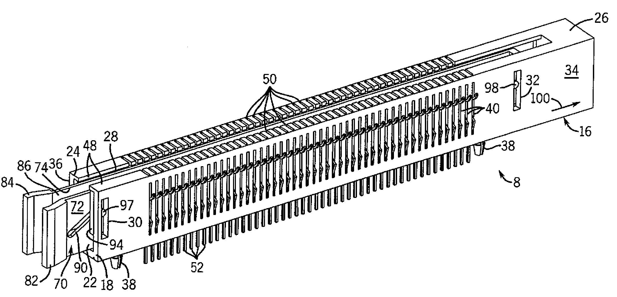
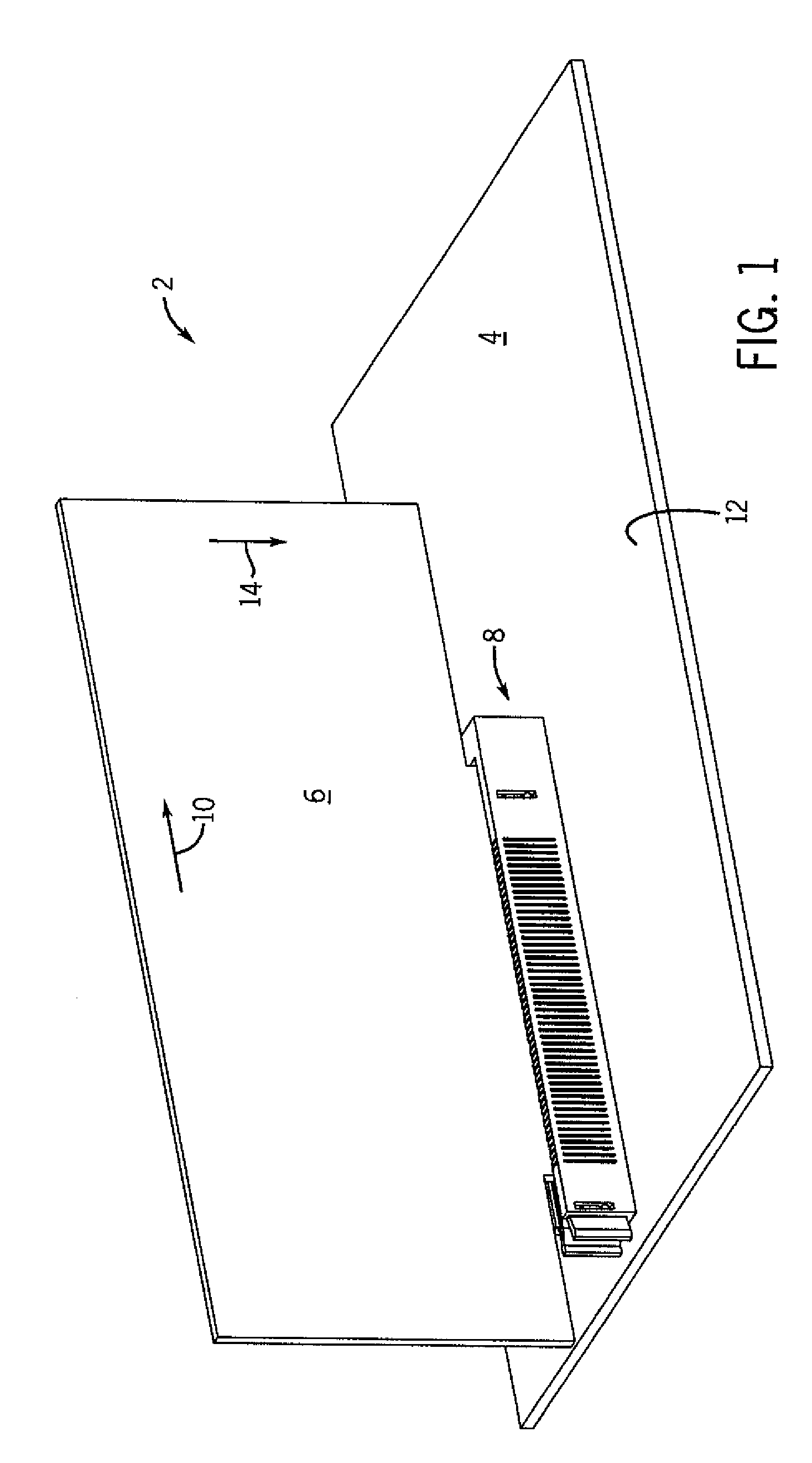
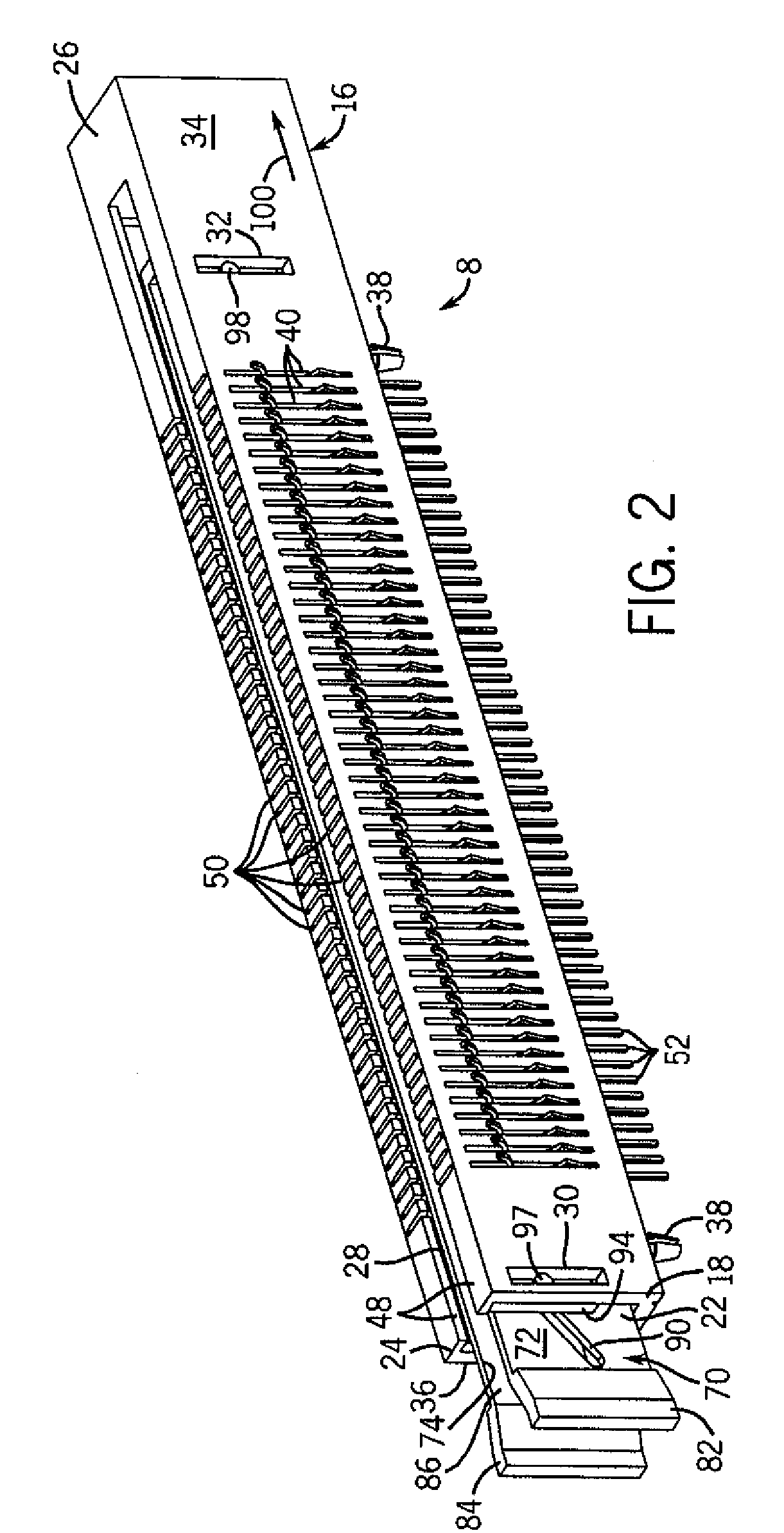
[0023]Referring to FIG. 1, an exemplary assembly 2 that can be implemented in a computer or other computerized device (not shown) includes a motherboard 4 and a daughtercard 6 connected together by way of a connector assembly 8. As will be described in further detail below, the connector assembly 8 facilitates the connecting or installation of the daughtercard 6 with respect to the motherboard 4 in an improved manner that involves merely the sliding of the daughtercard in the direction indicated by an arrow 10 that is generally parallel to a surface 12 of the motherboard 4, without requiring significant sliding movement along a direction indicated by an arrow 14 that is normal to the surface 12. Inversely, removal of the daughtercard 6 with respect to the motherboard 4 occurs by moving the daughtercard in a direction opposite to that indicated by the arrow 10, and does not require significant movement along a direction opposite to that indicated by the arrow 14. When the daughtercar...


PUM


Abstract

An apparatus and method for installing an electrical support structure, such as a printed circuit board or card in a computerized device, are disclosed. In at least some embodiments, the apparatus includes a connector assembly that includes a first structure having a first guiding surface, a second structure having a second guiding surface, a third structure having at least one additional guiding surface that interfaces the other guiding surfaces, and an electrically conductive component supported by at least one of the structures. Movement of the first structure in relation to the second structure in a first direction causes additional movement of the third structure in a second direction due to interaction among the guiding surfaces. Further, at least a portion of the component moves, in response to the additional movement, to or away from a first position at which the component is capable of establishing an electrical connection.

Description

CROSS-REFERENCE TO RELATED APPLICATIONS[0001]N / ASTATEMENT REGARDING FEDERALLY SPONSORED RESEARCH OR DEVELOPMENT[0002]N / AFIELD OF THE INVENTION[0003]The present invention relates to computerized devices, and more particularly relates to the assembly of components such as boards and cards within such devices.BACKGROUND OF THE INVENTION[0004]Computers and other computerized devices often employ boards (e.g., printed circuit boards), cards and other support structures on which are implemented various electrical devices and circuitry such as microprocessors, programmable logic devices (PLDs), and discrete circuit components. Often these support structures are intended to be modular such that the structures can be removed, replaced and / or added in relation to one another and / or other parts of a given computerized device. Typically, support structures of this type include connectors that are capable of being coupled to complementary connectors of other support structures or devices so that...

Claims


Application Information

Patent Timeline
Patent Type & Authority Patents(United States)
IPC IPC(8): H01R13/62
CPCH01R12/7023H01R12/87H01R12/89
Inventor RUBENSTEIN, BRANDON
Owner HEWLETT-PACKARD ENTERPRISE DEV LP
Why Eureka
Try Eureka