Enclosure-to-rail retaining system and method

a technology of enclosure and rail, applied in the direction of runways, ways, coupling device connections, etc., can solve the problems of enclosure being unintentionally disengaged from the rail, no longer being retained on the rail, and falling with potentially damaging consequences

Active Publication Date: 2008-05-20
GENERAL ELECTRIC CO
View PDF4 Cites 28 Cited by
  • Summary
  • Abstract
  • Description
  • Claims
  • Application Information

AI Technical Summary

Benefits of technology

[0007]Further disclosed herein is an enclosure-to-rail retaining system. The system includes, a rail that is fastenable to a structure and an enclosure with a channel, the enclosure being void any fixed portion that reduces a portion of the channel to a width less than the width of the rail. The enclosure also having a plurality of slots that each in

Problems solved by technology

Such a system, however, has the potential for the enclosure to become unintentionally disengaged from the rail if the enclosure is inadvertently bumped in a specific manner.
If this happens the enclosure will no longer be retained on the rai

Method used


Image

  • Enclosure-to-rail retaining system and method
  • Enclosure-to-rail retaining system and method
  • Enclosure-to-rail retaining system and method

Examples


Embodiment Construction

[0016]A detailed description of several embodiments of the disclosed apparatus and method are presented herein by way of exemplification and not limitation with reference to the Figures.

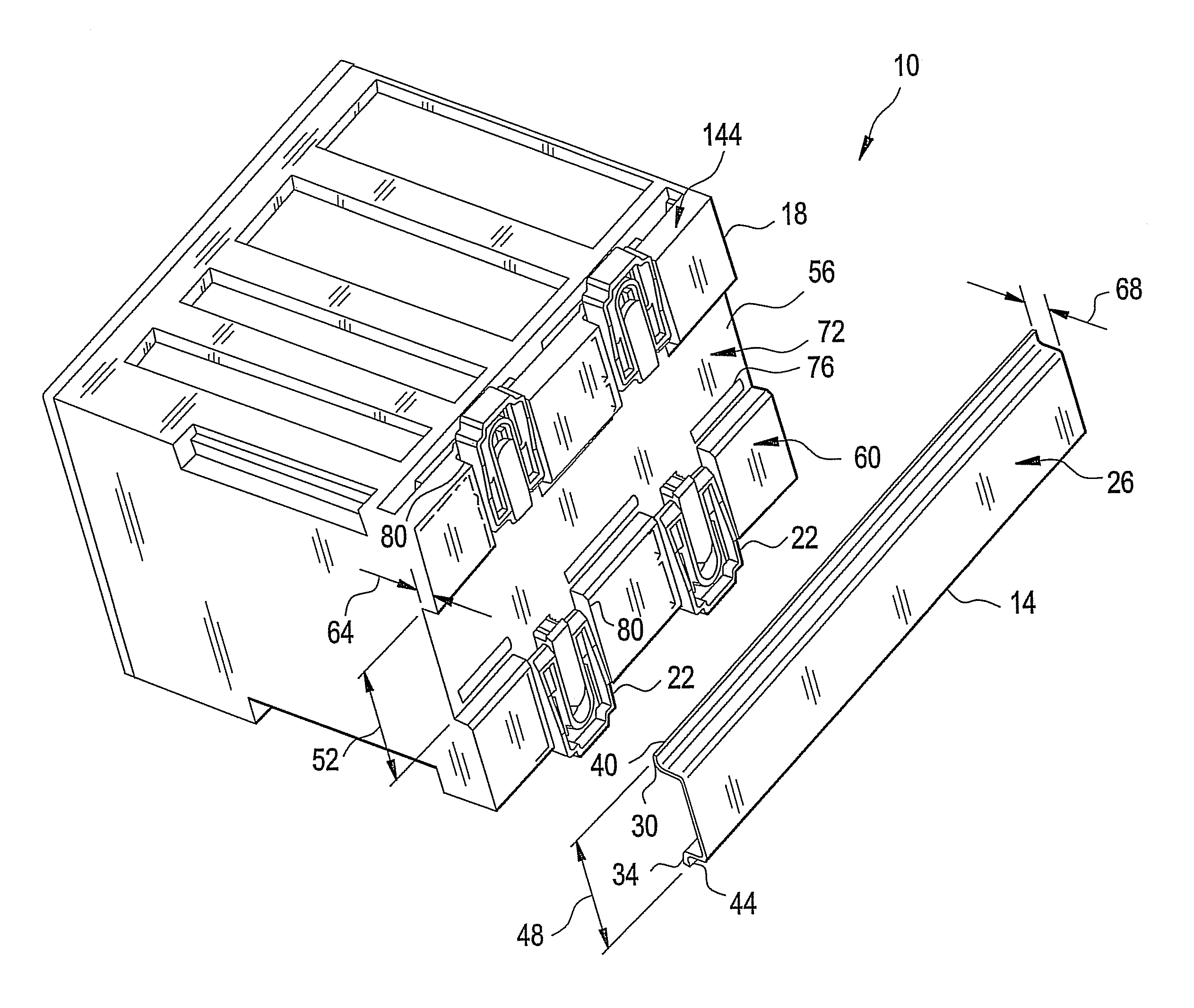
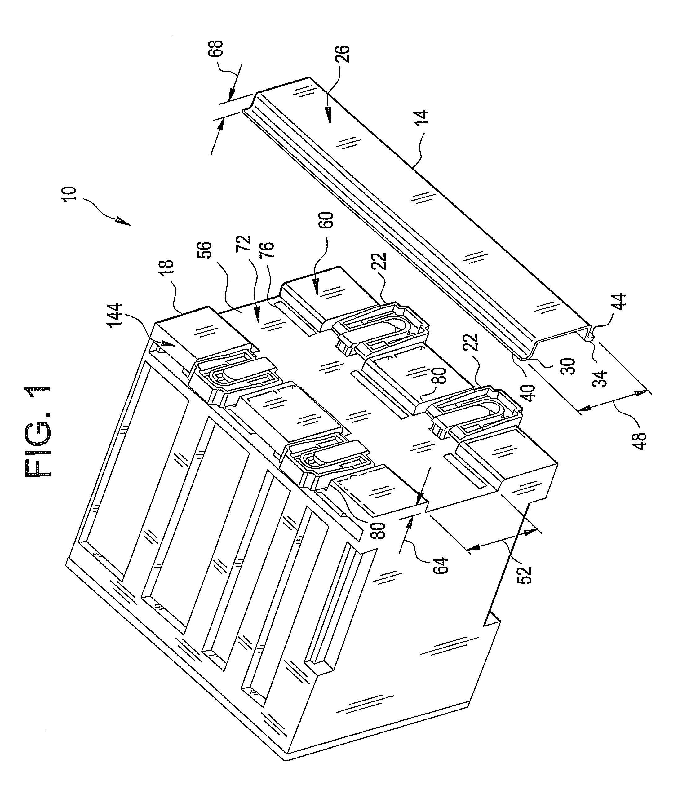
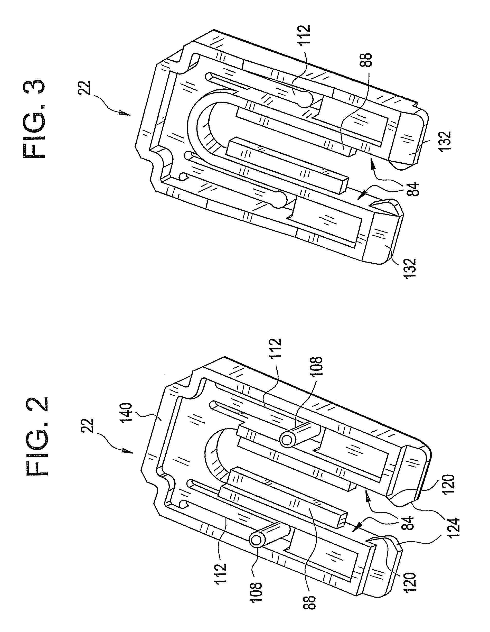
[0017]Referring to FIG. 1 an embodiment of the enclosure-to-rail retaining system 10 is illustrated. The enclosure-to-rail retaining system 10 includes a rail 14, an enclosure 18 and a plurality of clips 22. The rail 14 is mountable to a structure, such as a vertical wall or surface of a cabinet (not shown) for example, with screws, nails, clips, adhesive or the like. The rail 14 is a thin elongated member made of a strong rigid material such as metal, for example. The rail 14 can have a cross sectional shape that resembles a cross section of a top-hat and, as such, is commonly referred to as a top-hat rail. Top-hat rails are also referred to as DIN rails. DIN is a German acronym, which stands for, when translated to English, the German Institute for Standardization, which is Germany's ISO body. ISO ...


PUM


Abstract

Disclosed herein relates to an enclosure-to-rail retaining system. The system includes, a rail that is fastenable to a structure, and an enclosure that is receptive of the rail. The enclosure has a slot therein that intersects a channel therein and is slidably engagable by a clip such that a portion of the clip can extend into the channel to thereby narrow a portion of the channel to a dimension less than a width of the rail.

Description

BACKGROUND OF THE INVENTION[0001]A DIN rail is a standardized 35 mm wide metal rail with a top-hat shaped cross section. It is widely used, especially in Europe, for mounting circuit breakers and industrial control equipment inside equipment racks. In addition to the popular 35 mm top-hat rail several less widely used types of top-hat mounting rails have also been standardized. Top-hat rails are usually mounted in a horizontal orientation to a flat vertically oriented surface. In such an orientation the top-hat cross section provides an upwardly oriented edge and a downwardly oriented edge. The forgoing structure provides a strong stable mounting rail on which to mount enclosures that house a myriad of devices.[0002]Attachment of enclosures to the rail is typically accomplished by sizing a horizontal channel in a surface of an enclosure that is slightly greater in width than the width of the rail. Typically a downwardly extending lip on an upper sidewall of the channel engages with ...

Claims


Application Information

Patent Timeline
IPC IPC(8): H01R13/60
CPCB66C7/08H02B1/052E01B9/38H02B1/0523
Inventor ALLCOCK, DAVID JOHNTALUKDER, HAFIZ
Owner GENERAL ELECTRIC CO
Why Eureka
Try Eureka