Electronic device

a technology of electronic components and adhesives, applied in the direction of coupling device connections, electrical apparatus construction details, cabinet/cabinet/drawer, etc., can solve the problems of voids in the thermal adhesive member, difficult the inability to effectively release the heat generated from the electronic component to the support plate, etc., to achieve excellent heat radiation properties and eliminate or reduce the effect of remaining voids

Inactive Publication Date: 2008-05-20
DENSO CORP
View PDF17 Cites 40 Cited by
  • Summary
  • Abstract
  • Description
  • Claims
  • Application Information

AI Technical Summary

Benefits of technology

[0005]In view of the above-described problems, the present invention has an object to provide an electronic device capable of eliminating or reducing the voids remaining in the thermal adhesive member and providing excellent heat radiation properties.
[0006]In order to accomplish the above and other related objects, the present invention provides a first electronic device including a circuit board disposed on a support plate, with at least one electronic component mounted on the circuit board being accommodated in a recessed portion of the support plate. A thermal adhesive member intervenes between a rear surface of the electronic component and a bottom surface of the recessed portion of the support plate. According to the first electronic device of the present invention, the support plate has a communicating passage having one end opened to an inner space of the recessed portion and the other end opened to an outside of a layout region of the circuit board. Accordingly, the gas generating in the recessed portion of the support plate can easily go out of the recessed portion via the communicating passage. Thus, the arrangement of the first electronic device of the present invention can reduce or eliminate undesirable voids remaining in the thermal adhesive member, and accordingly can bring excellent heat radiation properties.
[0007]Furthermore, the present invention provides a second electronic device including a circuit board disposed on a support plate, with at least one electronic component mounted on the circuit board being accommodated in a recessed portion of the support plate. A thermal adhesive member intervenes between a rear surface of the electronic component and a bottom surface of the recessed portion of the support plate. According to the second electronic device of the present invention, the support plate has raised portions on its surface opposing to the circuit board for supporting the circuit board in a floated condition with a gap corresponding to the raised portions between the support plate and the circuit board. Accordingly, the raised portions cooperatively form a degassing passage between the support plate and the circuit board. The gas generating in the recessed portion of the support plate can easily go out of the recessed portion via the degassing passage. Thus, the arrangement of the second electronic device of the present invention can reduce or eliminate undesirable voids remaining in the thermal adhesive member, and accordingly can bring excellent heat radiation properties
[0008]Moreover, the present invention provides a third electronic device including a circuit board disposed on a support plate, with at least one electronic component mounted on the circuit board being accommodated in a recessed portion of the support plate. A thermal adhesive member intervenes between a rear surface of the electronic component and a bottom surface of the recessed portion of the support plate. According to the third electronic device of the present invention, the support plate has a communicating passage having one end opened to an inner space of the recessed portion and the other end opened to an outside of a layout region of the circuit board. Furthermore, the support plate has raised portions on its surface opposing to the circuit board for supporting the circuit board in a floated condition with a gap corresponding to the height of the raised portions between the support plate and the circuit board. Accordingly, the gas generating in the recessed portion of the support plate can easily go out of the recessed portion via the communicating passage. Furthermore, the raised portions cooperatively form a degassing passage between the support plate and the circuit board. The gas generating in the recessed portion of the support plate can easily go out of the recessed portion via the degassing passage. Thus, the arrangement of the third electronic device of the present invention can reduce or eliminate undesirable voids remaining in the thermal adhesive members, and accordingly brings excellent heat radiation properties.
[0011]This arrangement is advantageous because there is no possibility that foreign particles or substances stay between the sharp pinnacles of respective raised portions and the circuit board. Accordingly, the circuit board can be accurately supported on the support plate in a floated condition with an accurate vertical gap corresponding to the height of these raised portions.

Problems solved by technology

In this case, there will be the possibility that the thermal adhesive member includes voids and the heat generated from the electronic component cannot be effectively released to the support plate.
These voids will make it difficult to effectively release the heat generating from the electronic component to the support plate.

Method used


Image

  • Electronic device
  • Electronic device
  • Electronic device

Examples


Embodiment Construction

[0033]Preferred embodiments of the present invention will be explained hereinafter with reference to attached drawings.

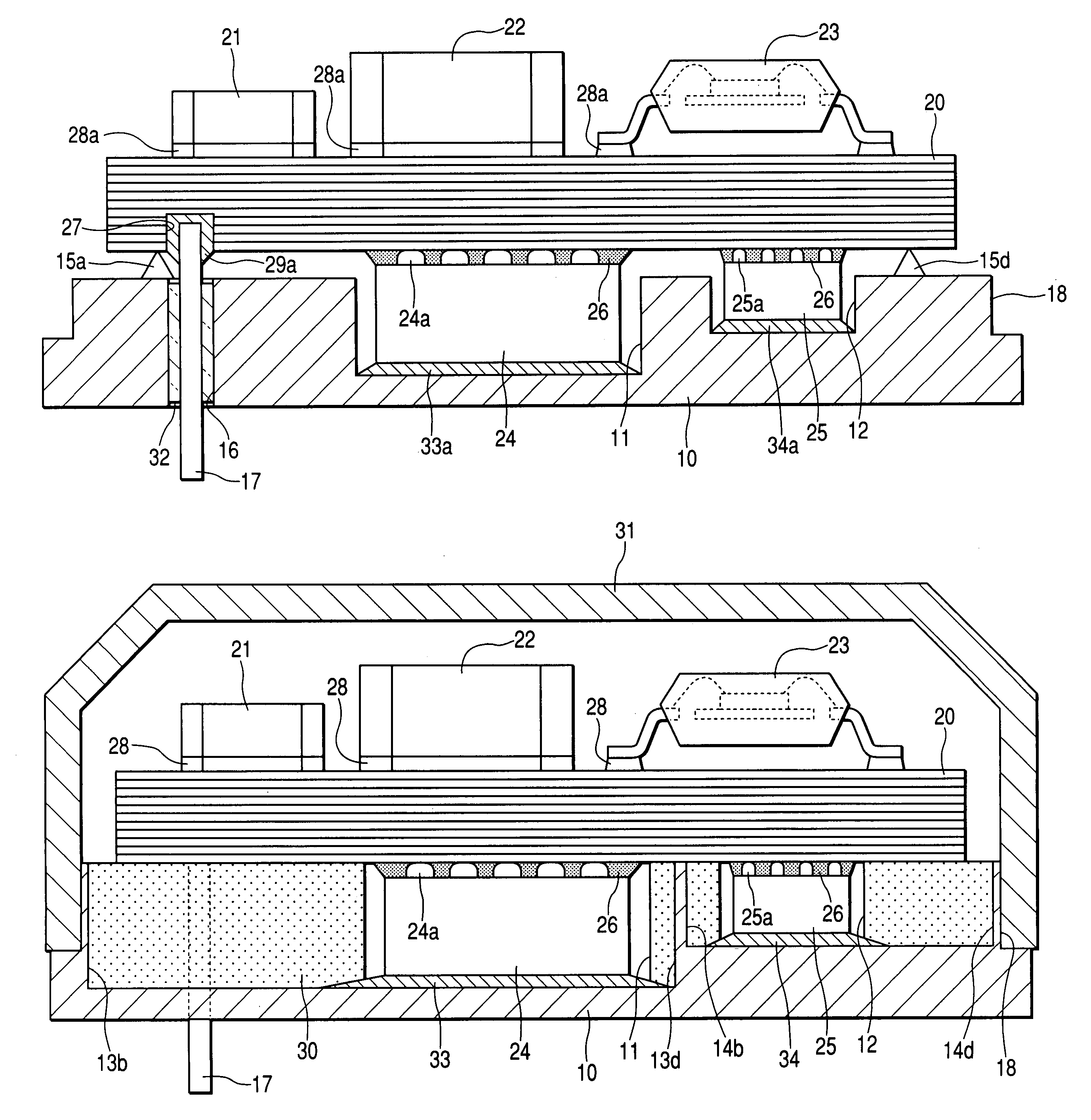
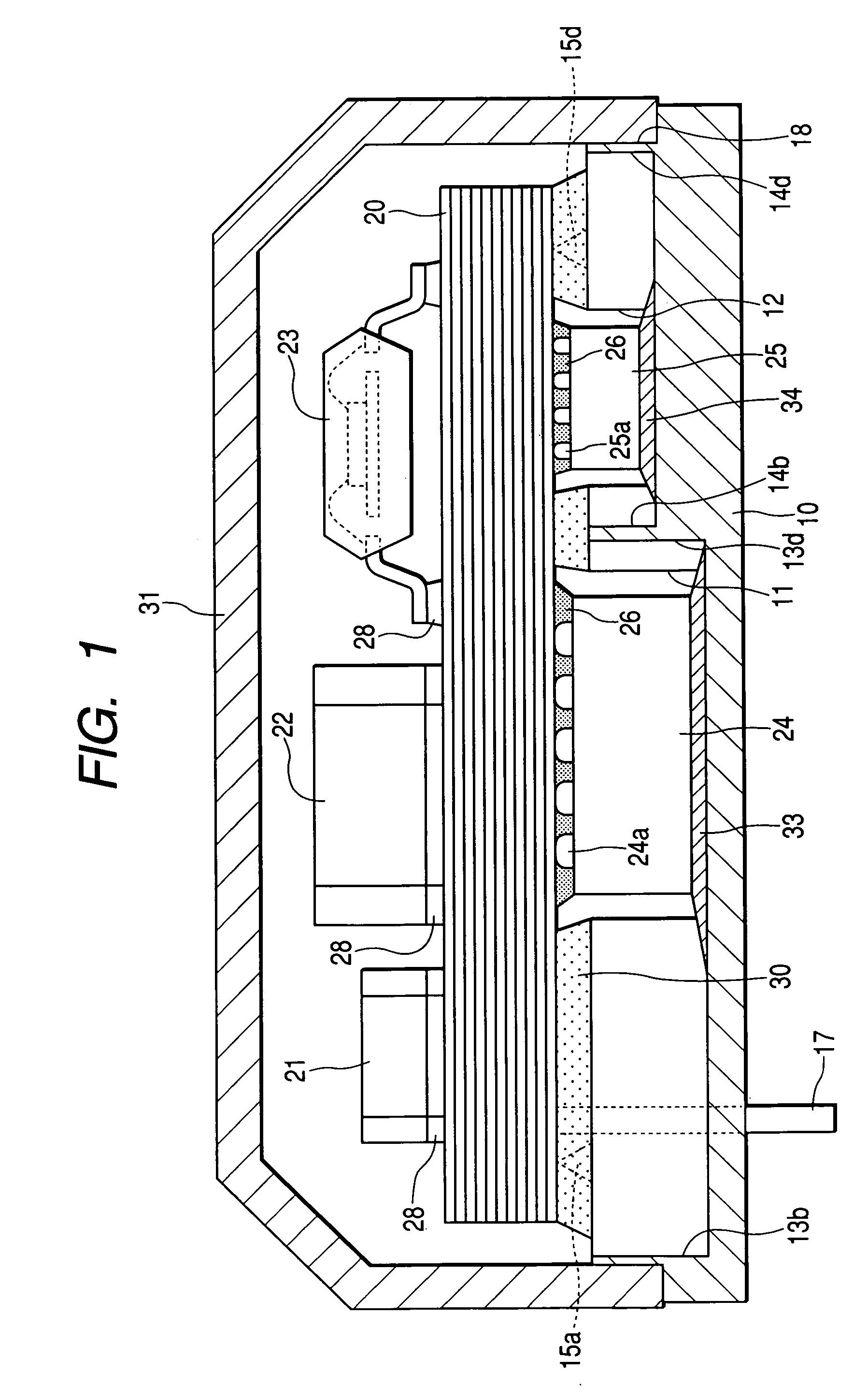
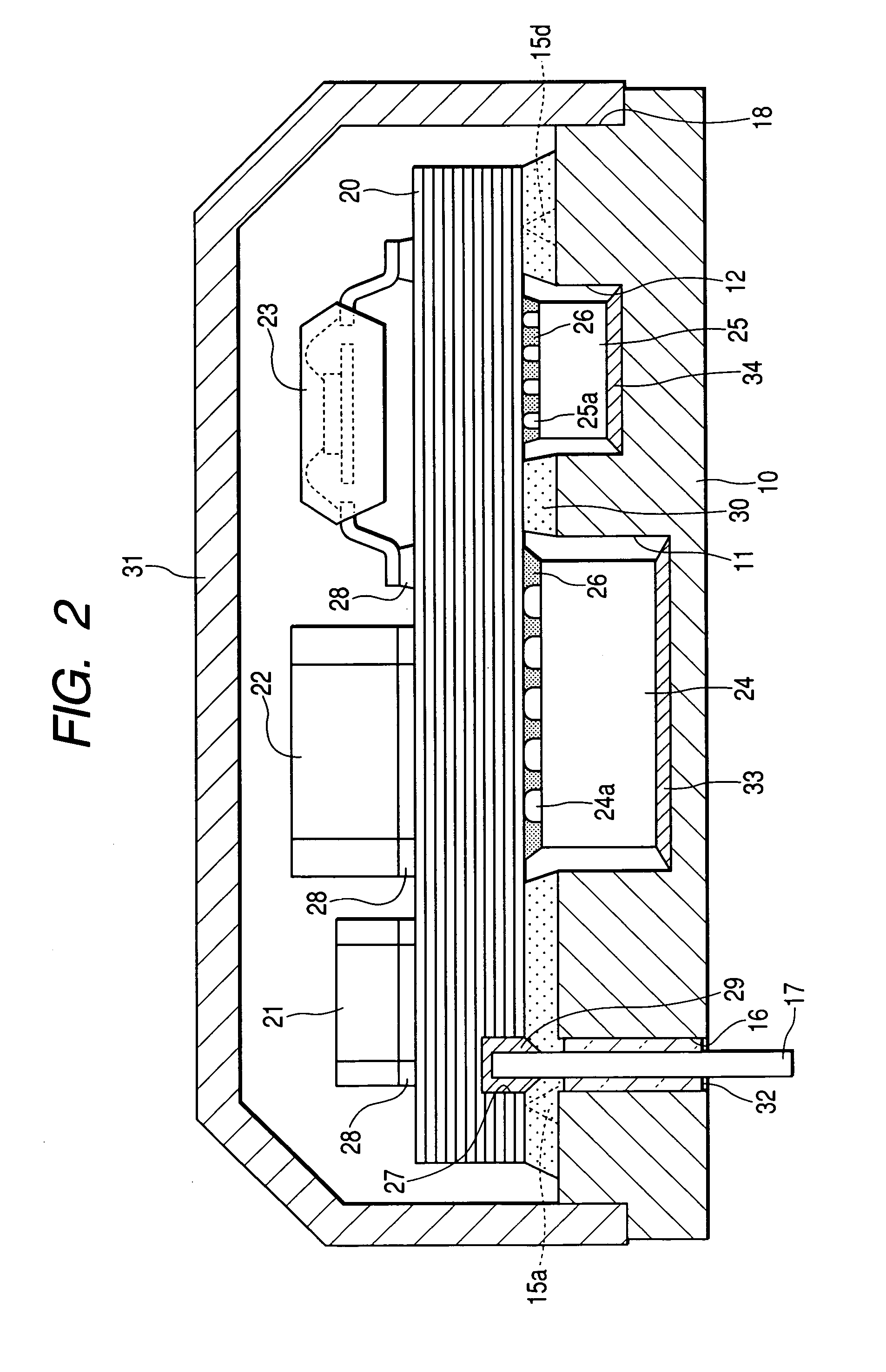
[0034]Hereinafter, a preferred embodiment of the present invention will be explained with reference to attached drawings. FIGS. 1 and 2 are vertical cross-sectional views showing an electronic device in accordance with a preferred embodiment. As shown in FIGS. 1 and 2, a circuit board 20 mounting various electronic components is disposed on a support plate 10. The circuit board 20 is covered with a cover 31. FIG. 3 is a plan view showing the circuit board 20, although the cover 31 is removed. FIG. 1 is a vertical cross-sectional view taken along a line 3A-3A of FIG. 3. FIG. 2 is a vertical cross-sectional view taken along a line 3B-3B of FIG. 3. This electronic device is an electronic control unit (ECU) incorporated in an automatic transmission of an automotive vehicle, which is compact, heat resistive, and reliable.

[0035]FIG. 4 shows the circuit board 20 together w...


PUM


Abstract

A circuit board is disposed on a support plate, with electronic components mounted on this circuit board being accommodated in recessed portions of the support plate. Thermal adhesive members intervene between rear surfaces of the electronic components and bottom surfaces of the recessed portions of the support plate. The support plate has degassing grooves. Furthermore, the support plate has raised portions provided on its upper surface for supporting the circuit board in a floated condition with a gap between them.

Description

CROSS-REFERENCE TO RELATED APPLICATION[0001]This application is based upon and claims the benefit of priority from earlier Japanese Patent Application No. 2004-73117 filed on Mar. 15, 2004 so that the descriptions of which are incorporated herein by reference.BACKGROUND OF THE INVENTION[0002]The present invention relates to an electronic device, and more particularly to an electronic device having an excellent heat radiation structure.[0003]As a conventional heat radiation structure for an electronic device, the U.S. Pat. application publication No. 2003 / 0148070A1 discloses a circuit board mounting an electronic component and disposed on a support plate. According to this prior art document, the ceramic body arranging the support plate is a porous member whose cavities are filled with aluminum. Furthermore, both surfaces of this ceramic body are covered with a metallic coat. The electronic component mounted on the circuit board is accommodated in a recessed portion of the support pl...

Claims


Application Information

Patent Timeline
Patent Type & Authority Patents(United States)
IPC IPC(8): H05K7/02H05K1/02H05K3/34H05K5/00H05K7/04H05K7/14H05K7/20
CPCH05K1/0203H05K7/20436H05K7/20854H05K3/0061H05K2201/09745H05K2201/1056H01L2224/16227H01L2224/32225H01L2224/32245H01L2224/48247H01L2224/73204H01L2224/73253H01L2924/15322H01L2924/16251H01L2924/19106H01L2224/16225H01L2924/00
Inventor KIRIGAYA, MASATO
Owner DENSO CORP
Why Eureka
Try Eureka