Signal peak reduction circuit for non-constant envelope modulation signals

a signal and envelope technology, applied in the field of circuits and methods for reducing the signal peaks of telecommunications signals, can solve the problems of amplifier saturation, large and costly amplifiers, and high power requirements, and achieve the effect of reducing amplifier saturation and reducing telecommunications signal peaks

Inactive Publication Date: 2008-05-20
PRESCIENT NETWORKS
View PDF5 Cites 17 Cited by
  • Summary
  • Abstract
  • Description
  • Claims
  • Application Information

AI Technical Summary

Benefits of technology

[0006]It would therefore be desirable to provide a circuit and method for reducing telecommunications signal peaks that minimises amplifier saturation without introducing unnecessary signal attenuation.

Problems solved by technology

Such amplifiers are large and costly, and have high power requirements.
However, the placement of the clipper 5 before the filter 4 can cause regrowth of the clipped peaks, which can again cause amplifier saturation.

Method used


Image

  • Signal peak reduction circuit for non-constant envelope modulation signals
  • Signal peak reduction circuit for non-constant envelope modulation signals
  • Signal peak reduction circuit for non-constant envelope modulation signals

Examples


Embodiment Construction

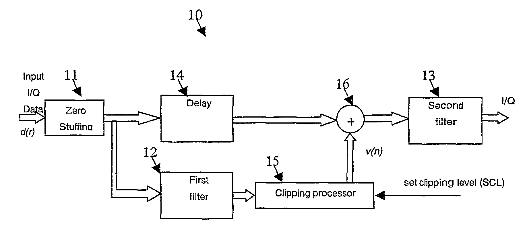
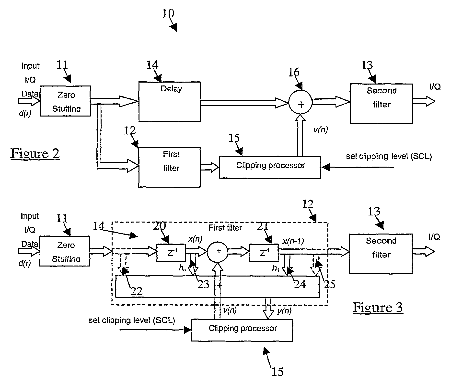
[0042]Referring now to FIG. 2, there is shown generally a schematic diagram of a signal peak reduction circuit 10 according to the present invention. The circuit 10 includes a zero bit stuffer 11, a predictive interpolation filter 12 and band-limiting filter 13, a delay line 14, a clipping processor 15 and a signal-summing device 16. Input I / Q data symbols, d(r), are zero stuffed by the zero bit stuffer 11 to form a signal x(n)—as shown in FIG. 4(a)—and then fed to two successive identical or closely matched filters 12 and 13 for interpolation. The filter 12 is a predictive filter that models the response of the second filter 13 and optionally any subsequent filtering prior to the P / A to the data bearing signal from the zero bit stuffer 11. The predictive filter 12 is used for predicting peaks in the data bearing signal and providing an output signal to the clipping processor 15 for generating the compensation signal in response to the detected peaks, in this case a correction vecto...


PUM


Abstract

Circuits for reducing the signal peaks in telecommunications signals are described. The circuits and methods are preferably adapted for reducing the peak to average power ratio of non-constant envelope modulation signals. In one example the circuit includes a band-limiting filter for limiting the bandwidth of a data bearing signal and a predictive filter for predicting peaks in the data bearing signal at the output of the pulse-shaping filter. The circuit also includes a clipping processor for generating a compensation signal in response to one or more signal peaks predicted by the predictive filter and a signal combining device for applying the compensation signal to the data bearing signal prior to amplification of the data bearing signal.

Description

BACKGROUND OF THE INVENTION[0001]1. Field of the Invention[0002]The present invention relates generally to circuits and methods for reducing the signal peaks in telecommunications signals, and in particular to circuits and methods for reducing the peak to average power ratio of non-constant envelope modulation signals. The present invention is suitable for use in applications involving multi-code Code Division Multiple Access (CDMA) signals, Orthogonal Frequency Division Multiplexing (OFDM) signals and critically sampled complex Gaussian signals, and it will be convenient to described the invention in relation to these exemplary applications. It will be appreciated, however, that the invention is not limited to use in these applications only.[0003]2. Description of Related Art[0004]Telecommunications devices that transmit signals with a high peak to average power ratio (PAPR), such as multi-code CDMA signals, require output power amplifiers with large peak power capabilities. Such a...

Claims


Application Information

Patent Timeline
Patent Type & Authority Patents(United States)
IPC IPC(8): H04B15/00H03K5/01H04B1/04H04B1/707H04J13/00H04K1/02H04L27/26
CPCH04B1/0475H04B1/707H04B2201/70706H04J13/0077H04L27/2623
Inventor BERANGI, REZAFAULKNER, MICHAEL
Owner PRESCIENT NETWORKS
Why Eureka
Try Eureka