Spar-type offshore platform for ice flow conditions

a technology of ice flow conditions and offshore platforms, which is applied in the direction of special-purpose vessels, vessel construction, transportation and packaging, etc., can solve the problems of major hurdle, drilling platforms may be severely damaged, and no proven floating system for petroleum and natural gas production from deep water

Active Publication Date: 2008-05-27
TECH FRANCE SA
View PDF11 Cites 27 Cited by
  • Summary
  • Abstract
  • Description
  • Claims
  • Application Information

AI Technical Summary

Problems solved by technology

Some of these hydrocarbon reserves are in deep water, and currently there is not a proven floating system for the production of petroleum and natural gas from deep water in areas where ice flow conditions are common.
Icebergs and ice flow conditions existing in the arctic regions create a major hurdle to deepwater drilling operations.
A drilling platform may be severely damaged if left to take the full impact of the crushing force of ice flow conditions or left to suffer a collision with an iceberg.
Many work hours as well as production hours are lost during removal of a drilling platform as a result of severe ice flow conditions or an approaching iceberg.
These systems are typically costly and / or impractical.
Further, these systems do not provide an efficient means for removal of the drilling platform in the face of an imminent iceberg collision.
Nevertheless, spar-type platforms can still suffer damage by ice flows, and destruction by icebergs, and are thus not suitable, in their present state of the art, for areas where these phenomena are prevalent.

Method used


Image

  • Spar-type offshore platform for ice flow conditions
  • Spar-type offshore platform for ice flow conditions
  • Spar-type offshore platform for ice flow conditions

Examples


Embodiment Construction

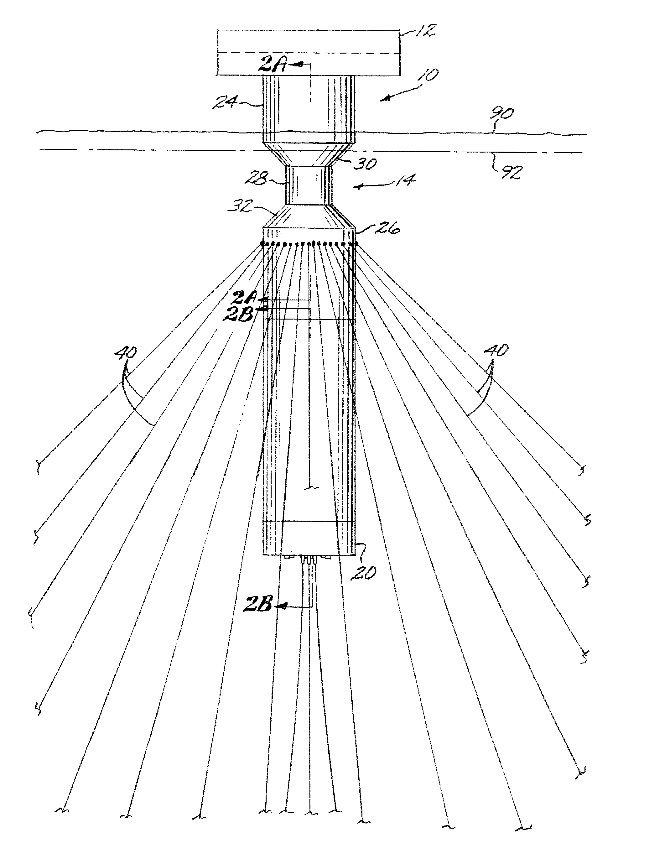
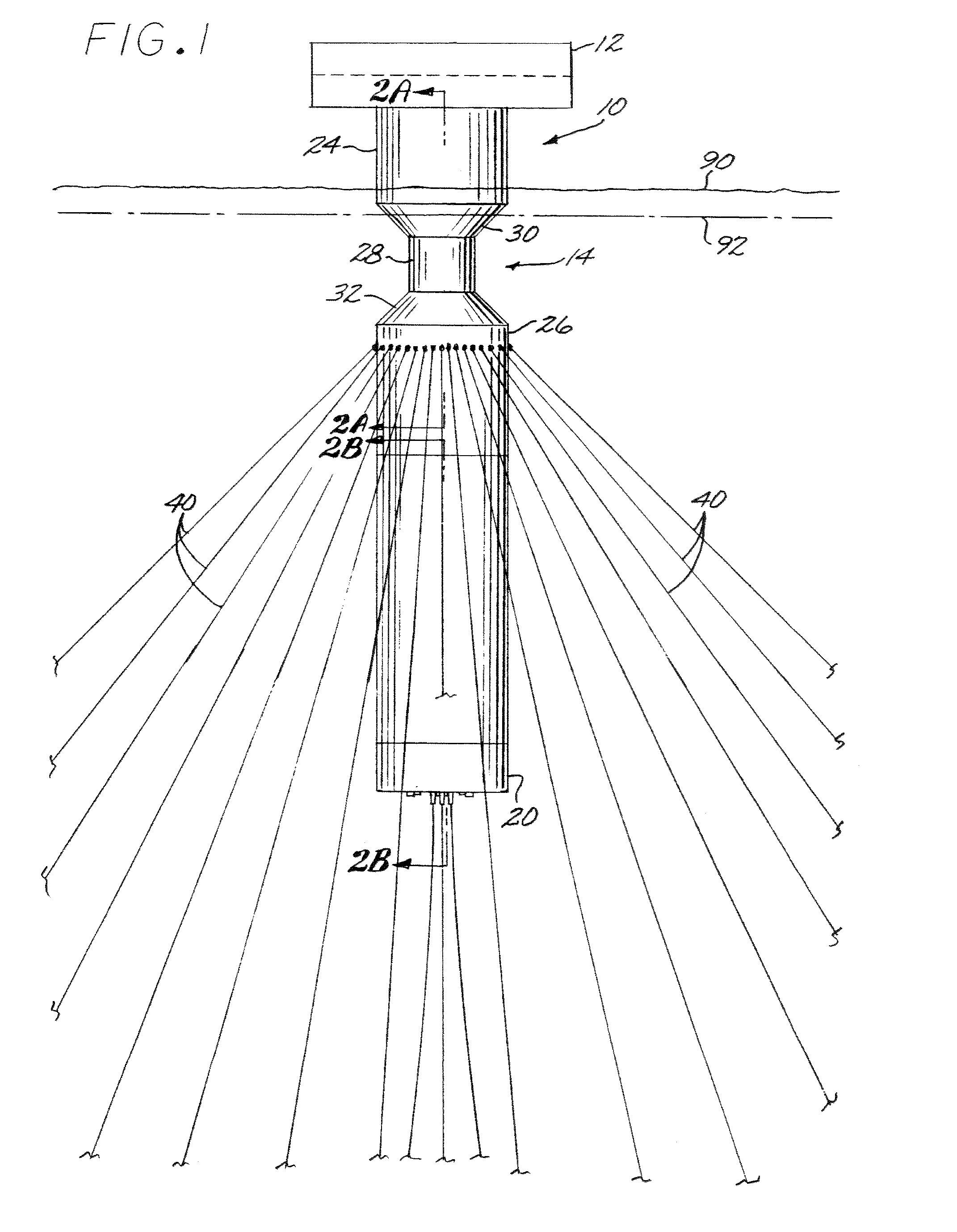
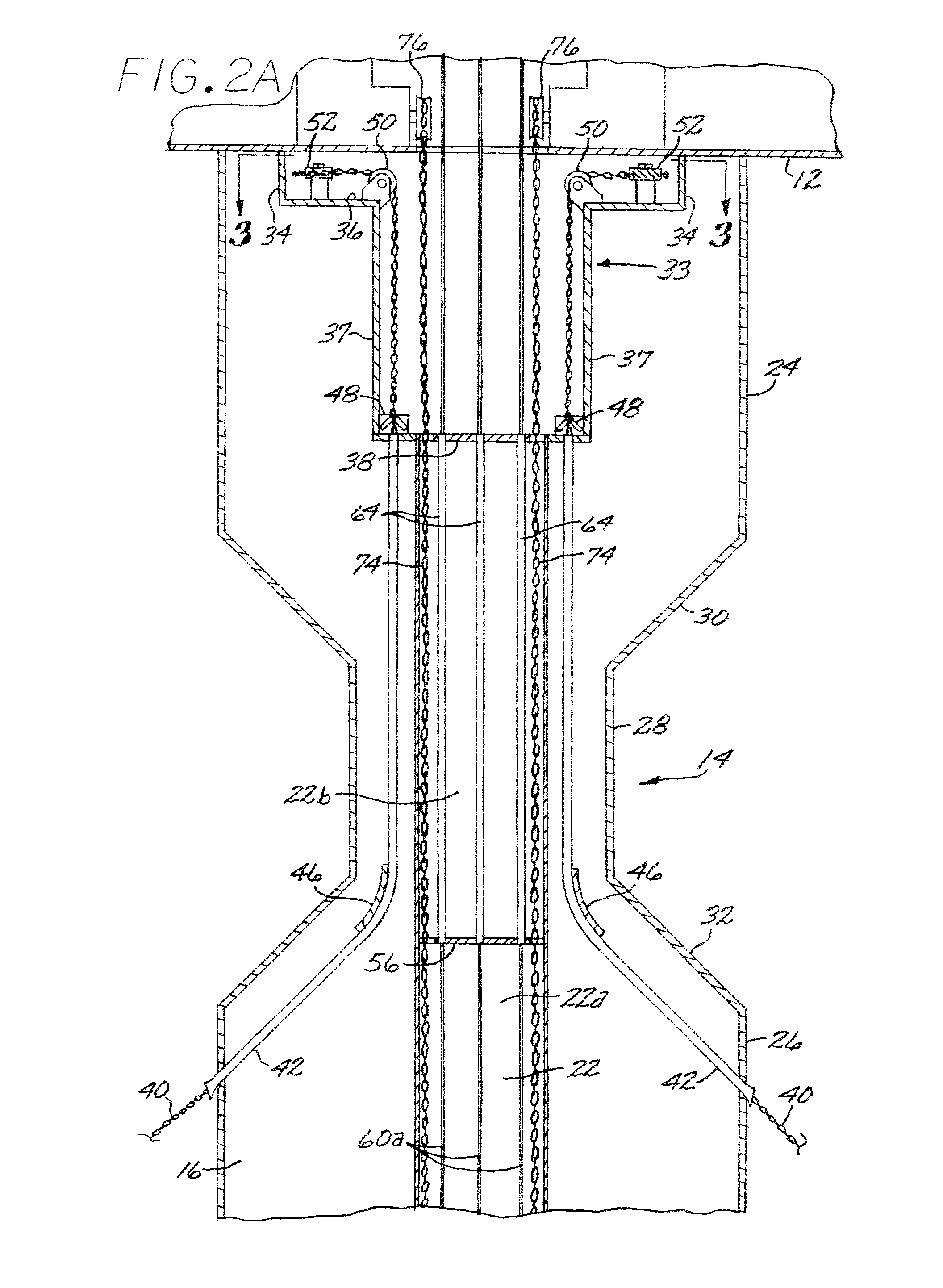
[0024]Referring first to FIGS. 1, 2A, 2B, 3, and 4, a spar-type platform 10, in accordance with the present invention, is shown. The platform 10 includes a deck 12 and a hull 14. The hull 14 includes one or more hard tanks 16, one or more skirt tanks 18 and a ballasted keel or keel tank 20. As is typical with spar-type platforms the platform 10 is provided with a mechanism (not shown) for selectively filling and evacuating the skirt tank or tanks 18 with seawater ballast, for purposes to be described below. The hull 14 defines an axial centerwell 22 to be described more fully below, that extends to the keel 20. The hull 14 has an upper portion 24 secured to the deck 12, and a lower portion 26 extending upward from the keel 20. Between the upper hull portion 24 and the lower hull portion 26 is a reduced-diameter neck portion 28 that is joined to the upper hull portion 24 by a tapered (e.g., frusto-conical) upper transition portion 30, and to the lower hull portion 26 by a tapered (e....


PUM


Abstract

A spar-type platform includes a hull defining a centerwell extending downward to a keel. The hull includes a reduced diameter neck portion for diverting ice flow. Adjustable ballast tanks allow the hull to be moved between a ballasted down position defining an upper water line, and a ballasted up position defined by a lower water line. A riser a support buoy is disposed in the keel. Risers extend through the centerwell, each having an upper portion extending upward from the support buoy and a lower portion supported in the support buoy. A disconnect system detachably connects the support buoy to the hull and the upper portion of each riser to the lower portion thereof, whereby the hull and the upper portion of each riser are selectively detachable from the buoy and the lower portion of each riser for movement to avoid a collision with a floating object.

Description

CROSS-REFERENCES TO RELATED APPLICATIONS[0001]Not applicableFEDERALLY SPONSORED RESEARCH OR DEVELOPMENT[0002]Not applicableBACKGROUND OF THE INVENTION[0003]The present invention relates generally to floating offshore production vessels for oil and gas, and in particular, to a deepwater spar vessel for ice flow conditions.[0004]The arctic regions of the world are known to contain appreciable hydrocarbon reserves (petroleum and natural gas), and exploitation of these reserves is likely to occur in the near future. Some of these hydrocarbon reserves are in deep water, and currently there is not a proven floating system for the production of petroleum and natural gas from deep water in areas where ice flow conditions are common.[0005]Icebergs and ice flow conditions existing in the arctic regions create a major hurdle to deepwater drilling operations. Ice flow from sheets of ice is caused by environmental forces, such as water currents and wind acting on the ice. A drilling platform may...

Claims


Application Information

Patent Timeline
Patent Type & Authority Patents(United States)
IPC IPC(8): B63B35/44B63B22/02
CPCB63B21/50B63B35/4406
Inventor FINN, LYLESTEEN, ATLE
Owner TECH FRANCE SA
Why Eureka
Try Eureka